Kaelble Z6W2A 130 - Heavy load tractor for the WWII German Army.
Note: I would like to have URL references to provide more insight into this relatively obscure vehicle, even though Kaelble made several hundred for the Germany army there isn't a lot of 'net based information available.
I've finally taken the time to put together a page for this model, the Kaelble Z6W2A 130. This was Jochen Maier's pet project. When I reconnected with him shortly after moving to my present home in 1990 he began telling me of his new project, he apparently had begun work on it some while after stopping the sales of his original 1/10 scale Panther A. At this time the 'net as we know it had not really blossomed and he didn't yet have a presence there. Information was limited to faxed copies of photos of the original. It wasn't until I visited Jochen on a trip to Germany in 1996 that I had the chance to see his prototype model. At that time we struck a bargain where I was to purchase a model from him at a 'friend's price' ( which was still quite a bit) however later necessary work on my home precluded this. As often is the case way led on to way and we never revisited this and the opportunity passed. When Jochen sold his business later prices increased pushing the model quite a way beyond my comfort level. I later placed a 'wanted' post on a German armor forum and that turned up, ultimately 3 machines in various states but none nearly complete. Two were 'standmodell' or static versions without mechanics and the third having a functional drive. I was able to get Jurgen Stehr to upgrade the rear axles to functional state on the first of the static models and I was able to making a functional 'diesel' engine in the same manner as sold by Hr Stehr using tandem 540 class electric motors. Below is a list of what I have thus far.
What follows will detail my work with these models. Since these are still sold by Jurgen Stehr I wish to say that any parts I may make for these are for my own use only and while I am willing to share technical knowledge gained in working with these models I am not at this time willing to sell any parts made by me which are in conflict with original work by Mr Stehr.
Two photos to start off, I'll replace these. Every time I start a new project I have that feeling of being at the base of a new mountain looking up the side; there's a ways to go. No, I've not given up on my other projects, rather they're awaiting parts, creative urges, insights.... you know- all that jazz. Give up, never! As you recall I started a project on two other King Tigers but other things popped up with that and I followed a different path for a while when I thought I might be getting involved in a joint parts project but that seems unlikely now. I can work in tandem. Several of my projects have been waiting on parts or ways /means of getting/making parts to higher standards than in the past so some projects get stretched out. These Kaelble trucks will very likely be 'filler' projects and very likely they themselves will be temporarily suspended while I work out getting parts or how to make some items. The Kaelble trucks have the benefit of being electric, removing an entire layer of consideration I face in many of my glow powered tanks. In the final analysis if I want to continually engaged with a model project I have them, I'll likely never run out of things to do.... Jerry 02/22/2019
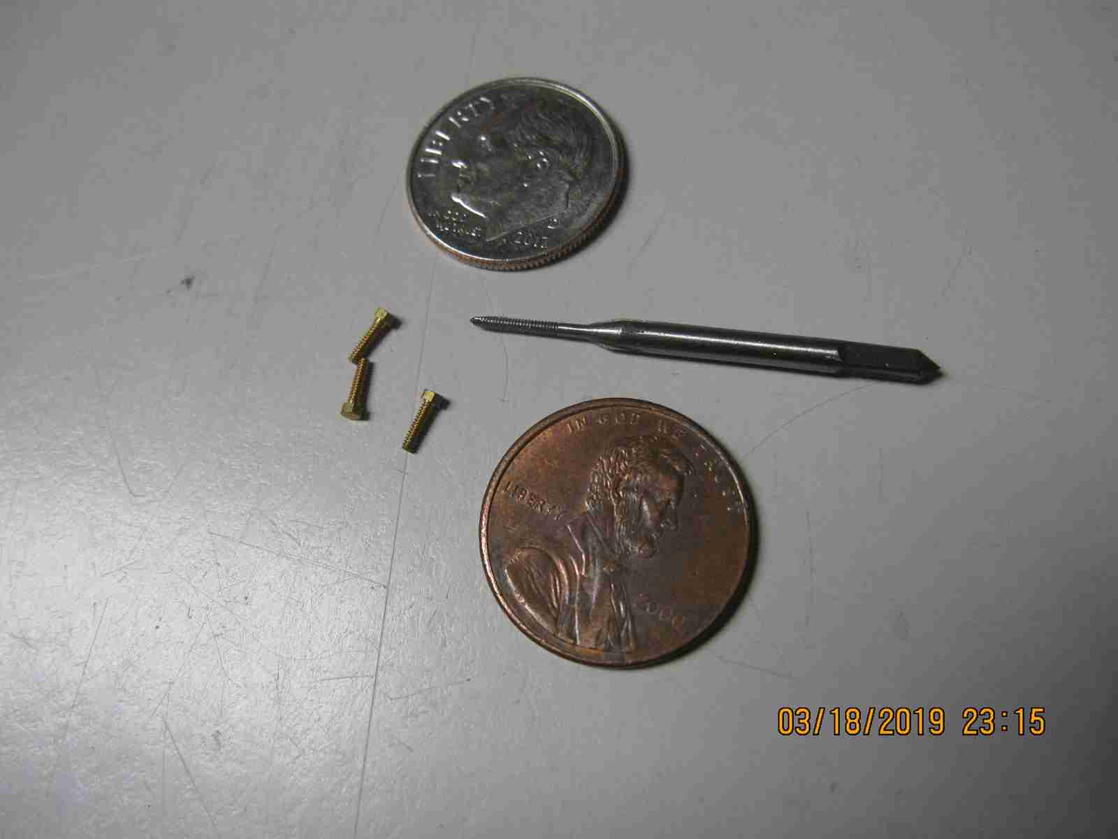
I'm busy cutting .080"(~2mm) and .125" (3mm+) aluminum sheet for the rear body of two of my trucks. Probably one of the messiest operations I've done as I'm using a Worm drive skill saw to cut the rough sized pieces/strips from a much larger sheet then using a small Dremel table saw with a very efficient carbide tipped 48 tooth blade to make the smaller pieces. Messy in the extreme and I'm obliged to use both a face shield and mask. I'm nearing completion on the first pass through the parts; next will be to make holes, openings and other facilities on the cut parts. Stehr( and perhaps Maier began this??) has made milled channels on his body parts with the intent, I'm assuming, that the parts be bonded together with an advanced adhesive. I'm not going to do that. I plan to butt my parts to each other end to surface and fasten them together with small aluminum angle and 2mm flat head stainless screws. Wherever the screw heads are visible I intend to conceal them with either a strong bonding filler or JB weld. I rather like the possibility of being able to disassemble the parts in the event of modification or repairs. I have to make my body parts smaller in those dimensions which depended on the slotted joints as I'm not using them.. Hoping it will all work well. Jerry 03/02/2019
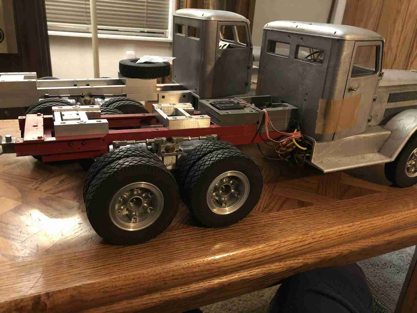
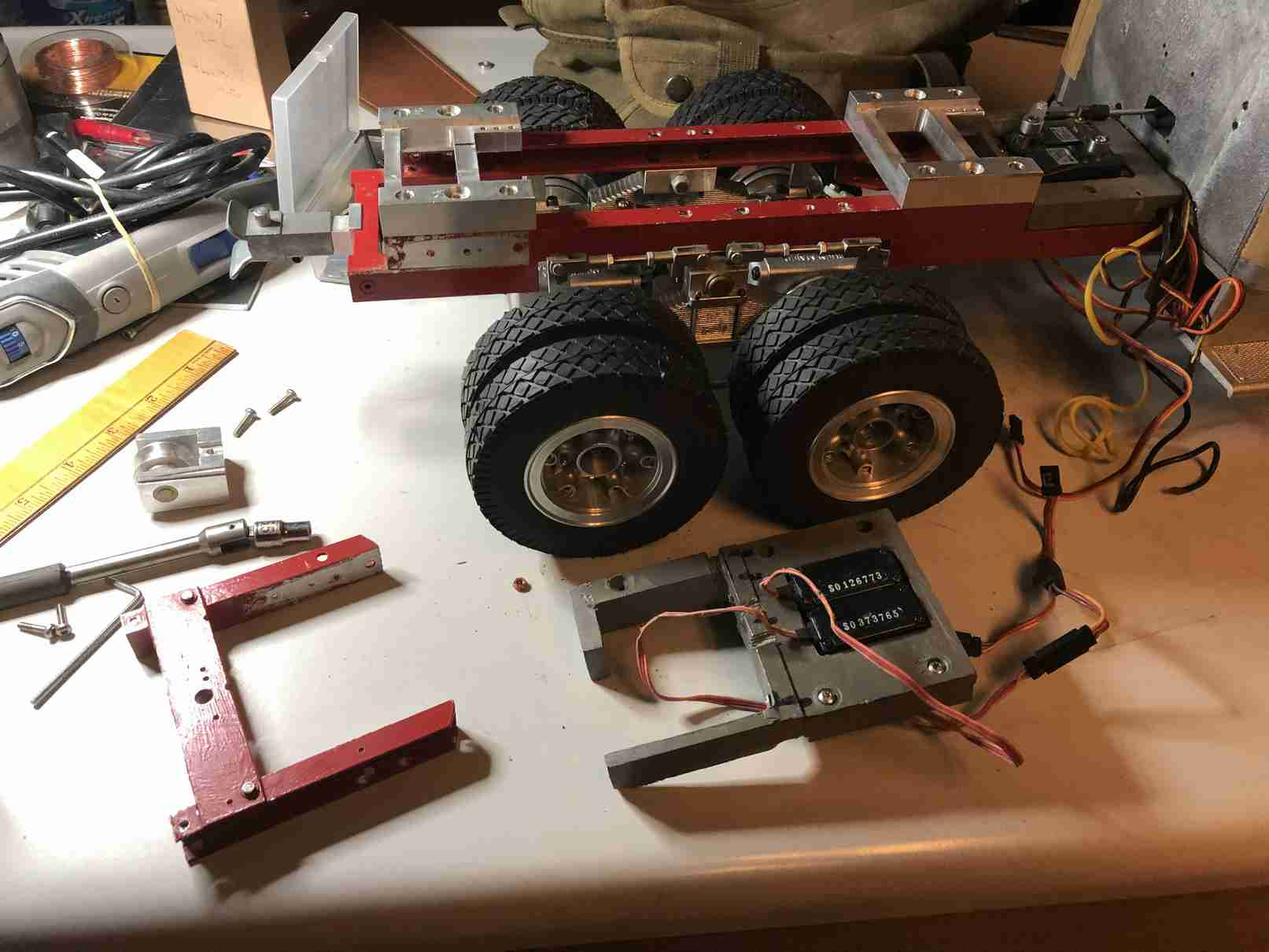
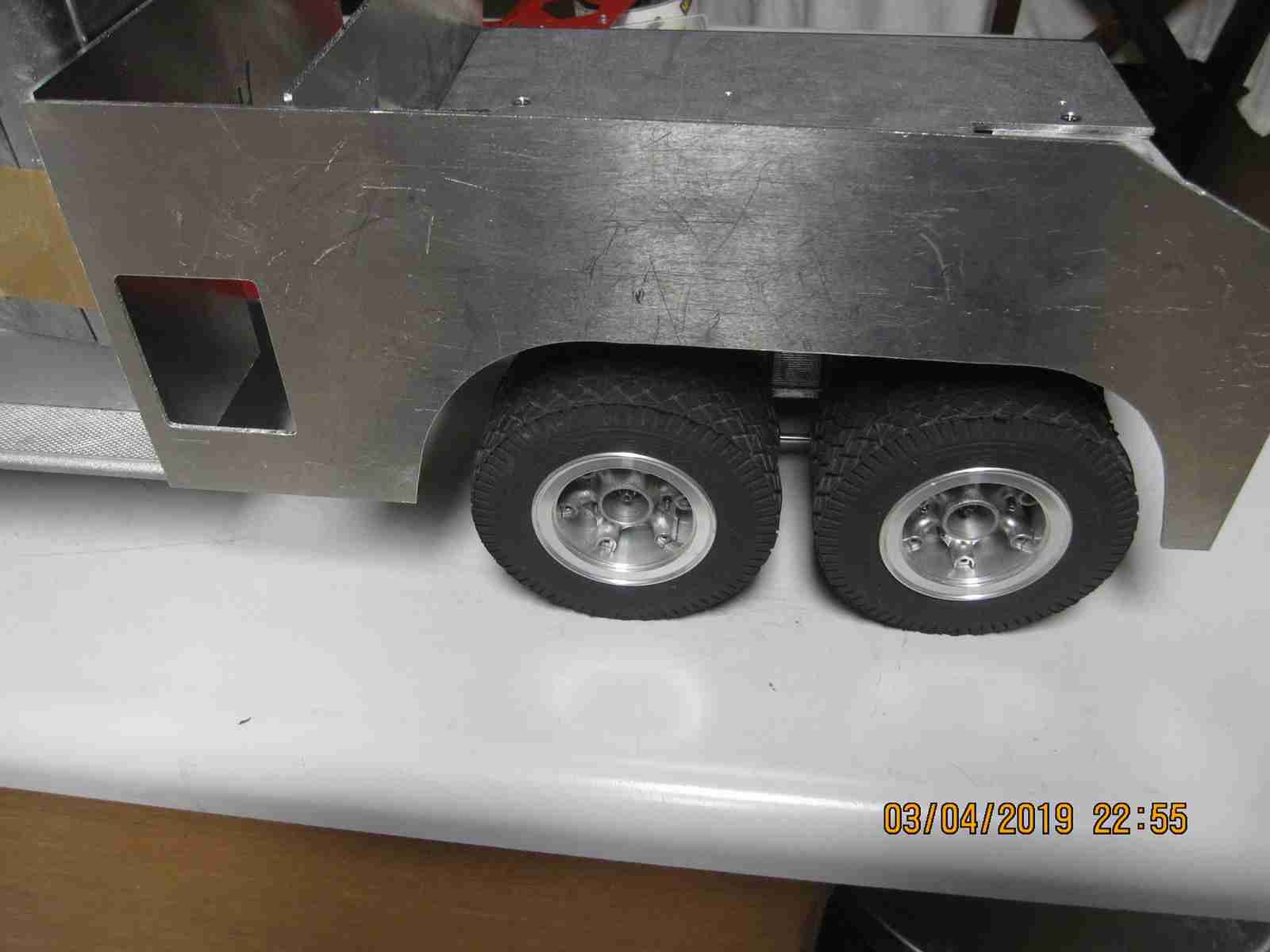
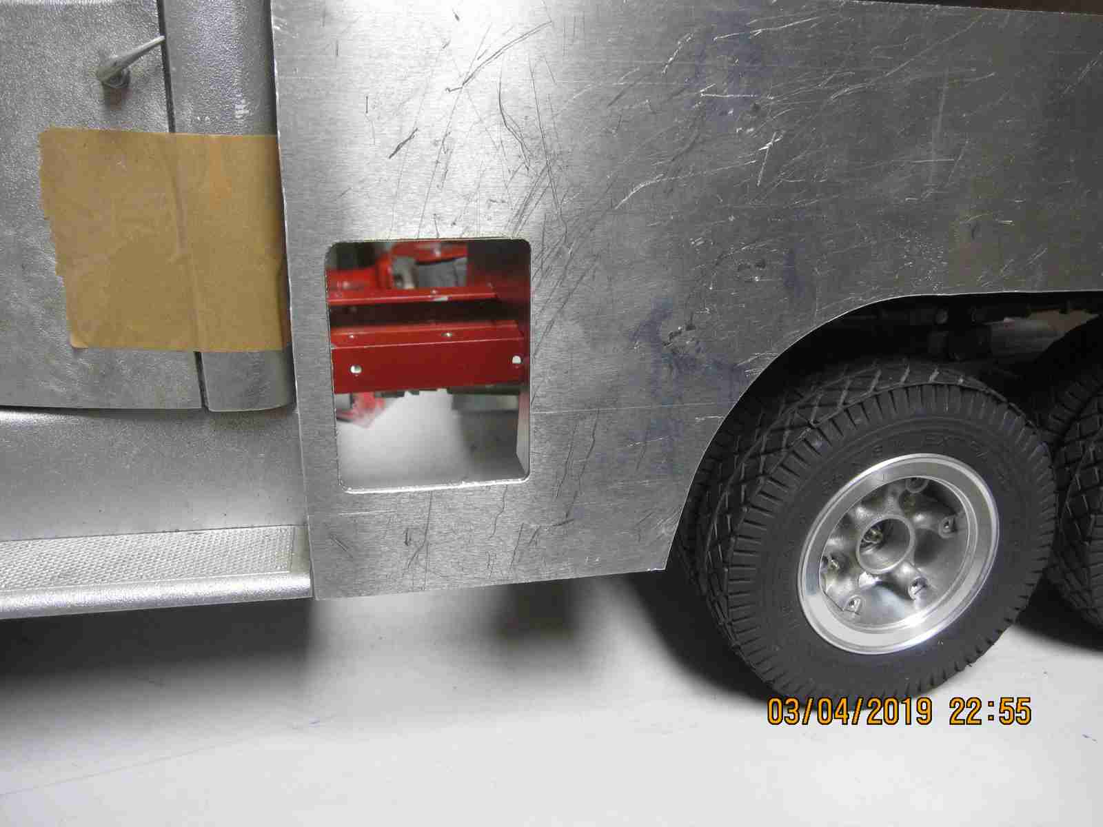
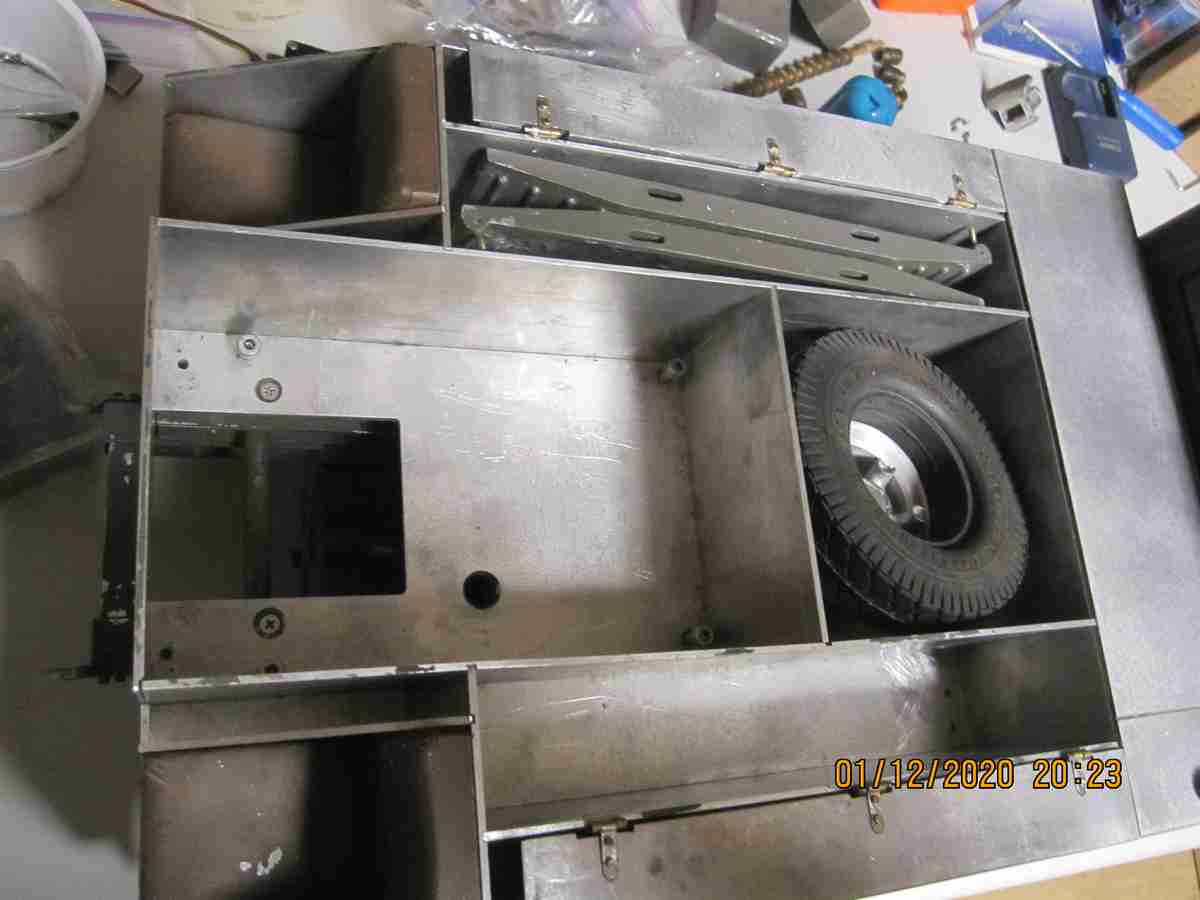
I'm really wanting to be done with making the aluminum sheet body parts. Cutting out the parts, there are at least 21 pieces for each body super structure is about the messiest function I've had to do. I don't like it and if I could have purchased these parts easily I would have. While the major part of the work is done there's cutouts, holes and alignment slots to cut. I may have already said the original appears to have been designed to be glued together, to a greater extent something I'm hoping to avoid. Still I'm going to try cutting the alignment slots with my Dremel table saw. It has zero issues cutting the .080" and .125" thickness aluminum; the carbide blade I purchased cuts it like butter but the mess is over the top. I have aluminum sawdust everywhere and I've been using a mask every time I cut. I don't expect to have issues cutting the alignment slots that I want I just don't want to have to cut them! I think I can get away with just a few 'strategic' cuts, at least so I'm hoping... Below are photos of trial fitting of a few plates held together with cellophane packaging tape; the parts sag out of alignment quickly but gives an idea of how things begin to take shape. I'm not sure what the original owner of this Kaelble had planned for it and I've been forced to remove the servos they had mounted to operate the transmission and differentials as the body plates would not fit over their implementation. I will relocate the servos when the body is complete. Jerry 03/04/2019

The rear superstructure/body is coming along nicely. I find using the aluminum angle with 2mm stainless steel flathead screws is working very well and is actually proceeding faster than I thought. As these pieces are copies of those that were intended to be assembled differently some fitting and adjust needs to be done but so far this hasn't been significant. Working with the thin material (~2mm) is actually refreshing, Jerry 03/06/2019


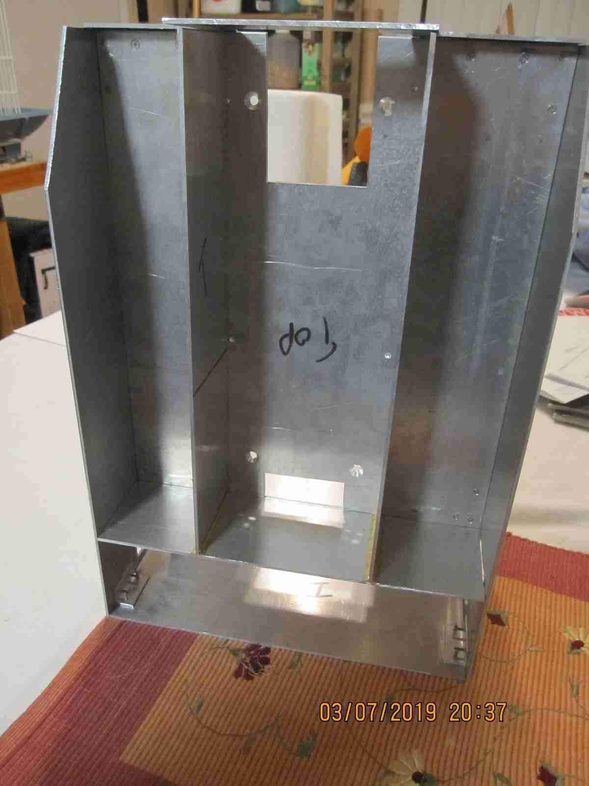
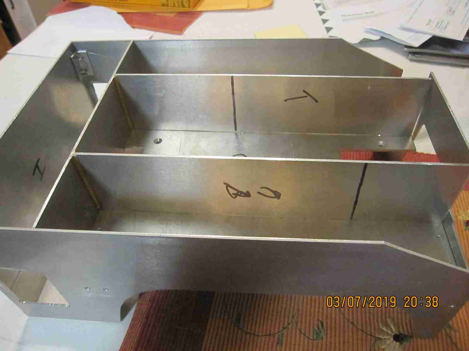
Mounted the front plate and partially the two longitudinal separators. I didn't use my usual aluminum angle as it would be relatively unsightly in this location. This will also be the case with other parts of the body that are fully or partially exposed. I decided the rivet in thin brass angles, one on either side of the part it is to hold however I do not fasten the held plate to these angles rather they provide a channel in which the plate may be slid into. I'll take a close up later but this also affords the ability to take out the internal member. I believe all of them may be held in this way with some being held by mutual support and securely. More to follow. Jerry 03/07/2019.
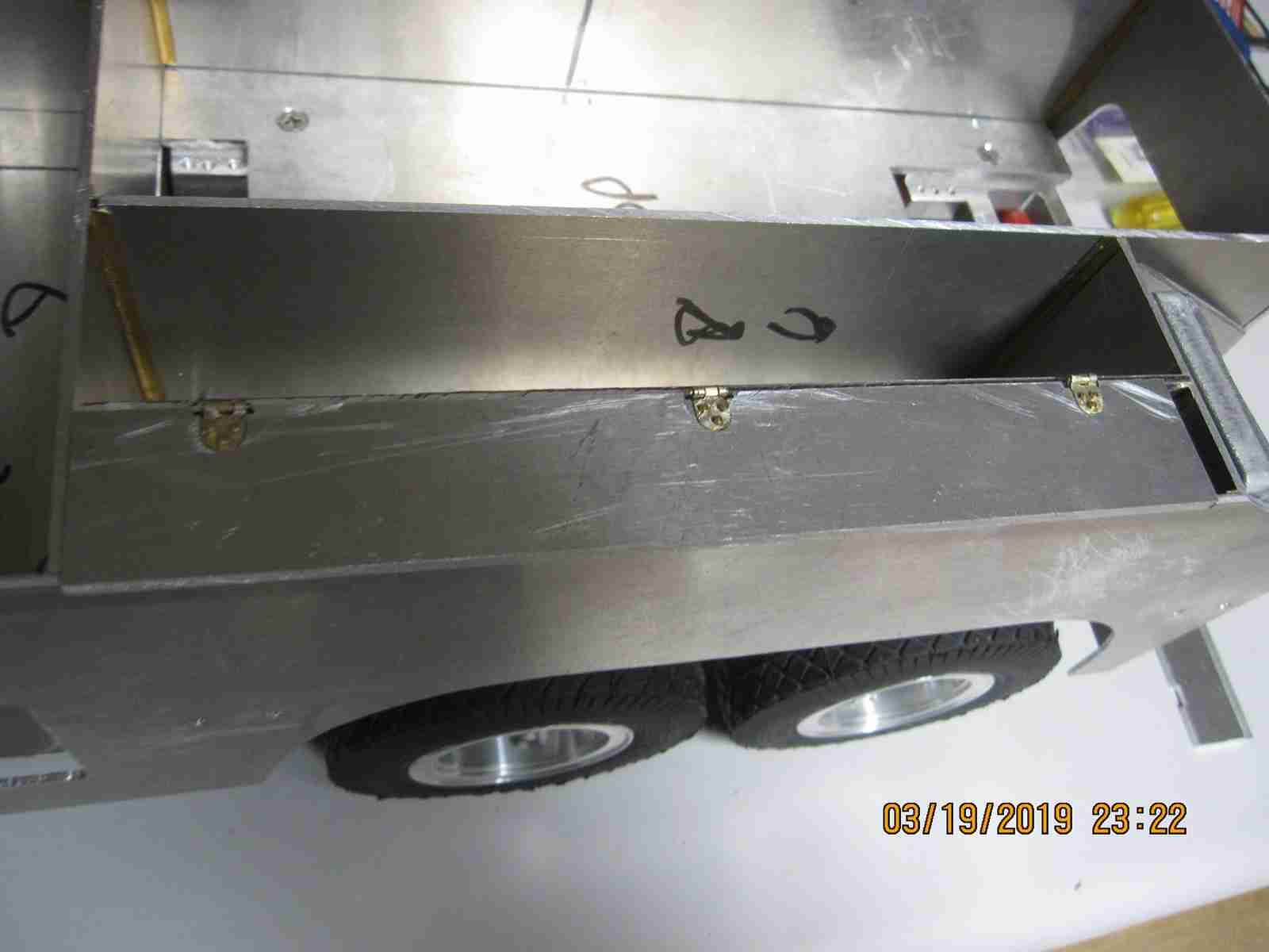
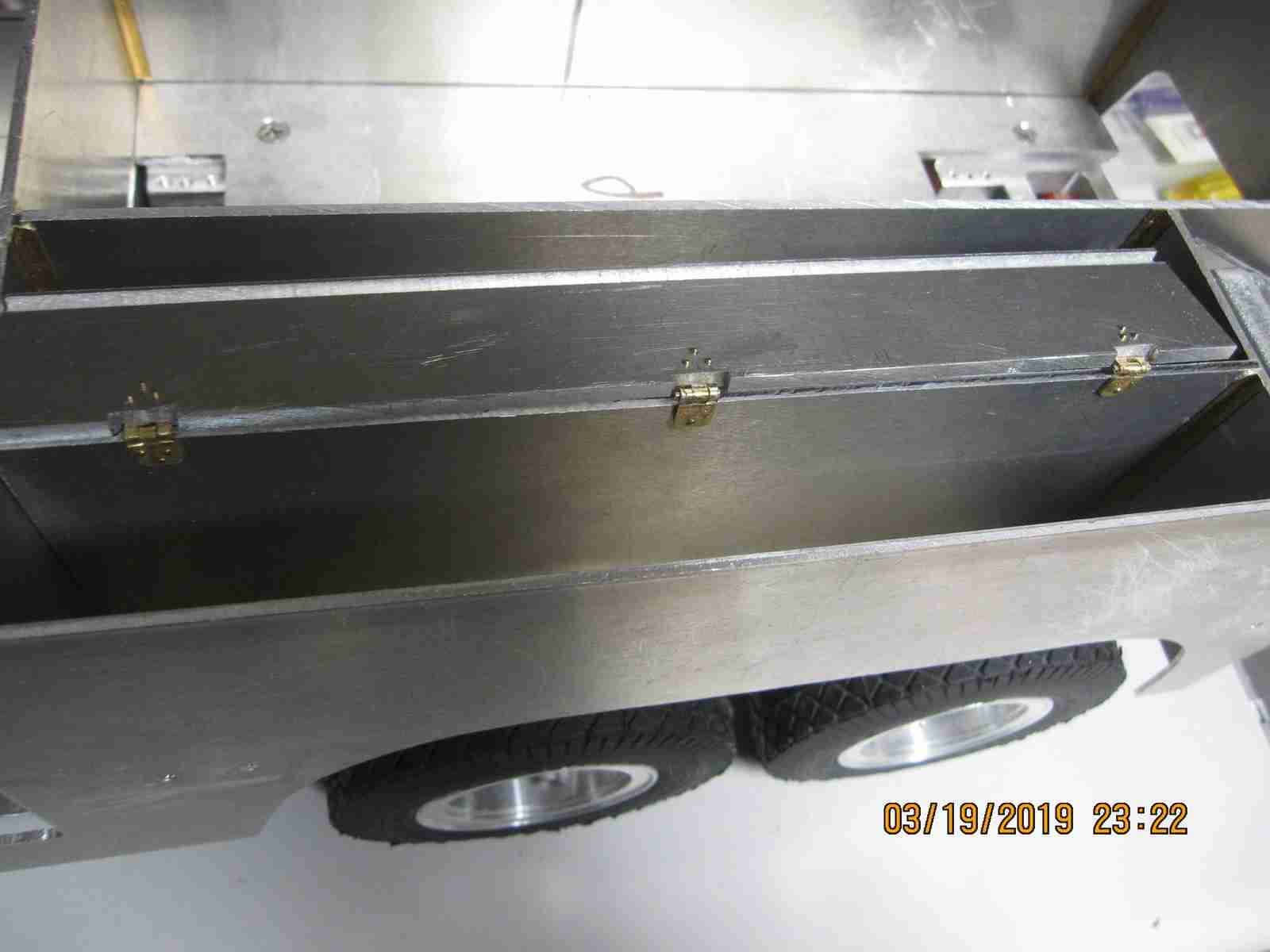
I've been working on the two sand ballast bins on the model. As far as I can determine these were filled with sand used to give the full sized truck traction and stability by adding weight, Also I believe, however I've not been able to prove this, it was possible to empty these bins but moving a lever on the side of the rear upper body above and forwards from the wheel well. This lever, it is my contention would open a slide which allowed sand to escape from the bottom of the bin and exit between the rear wheels via a form of chute. This chute is molded into the cast aluminum fenders and it is my intent to may this feature a functional one. My last several days have been spent making the bin lids, hinges and assembling these. You made see the trial fitting of these parts in the photos below for the left side bin only. There is one thing that I should point out and that is the length of the ballast cover; it doesn't extend all the way to cover the entire bin. This is by design but I'm not sure why as it surely looks odd or that it was a mistake. It isn't. The only reason I could come up with was to allow access to the sand without opening the bin?? Most odd. Jerry 03192019
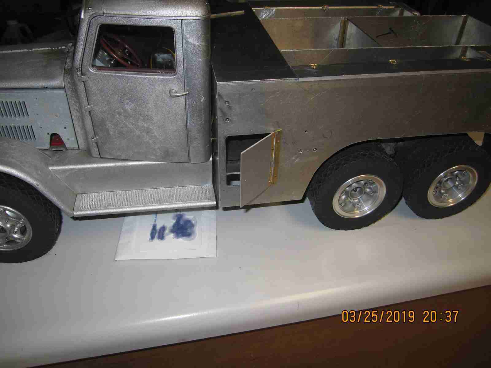
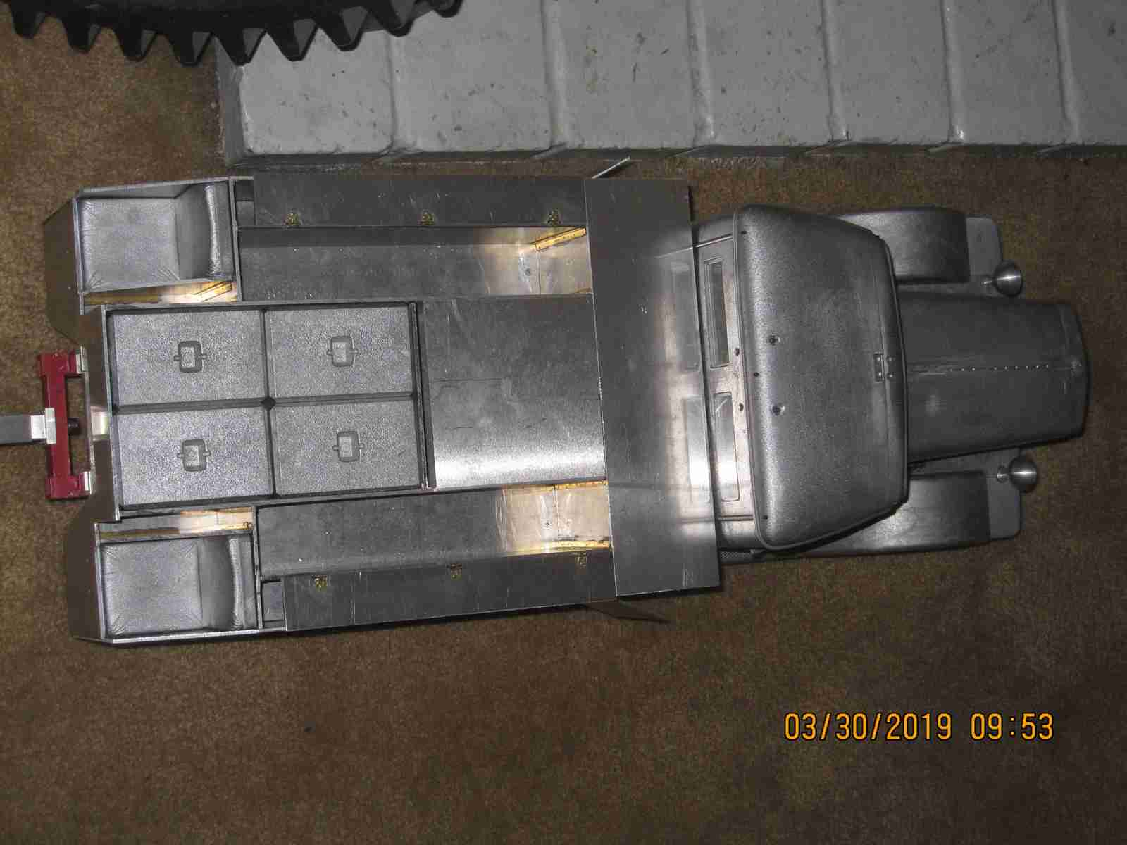
I've installed most of the structural members for the body, time consuming bits were making the hinges needed for both the ballast bins and the side access doors. In the two photos below the progress may be seen. Jerry 03/26/2019

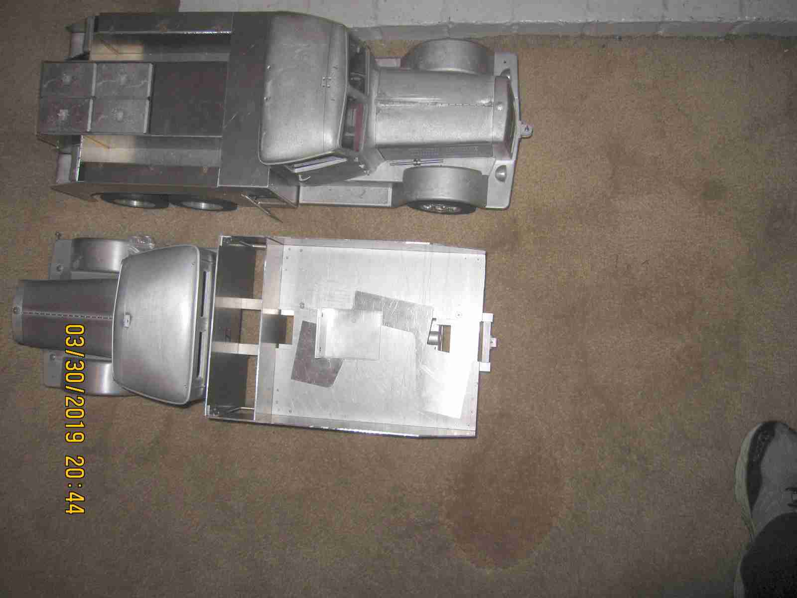
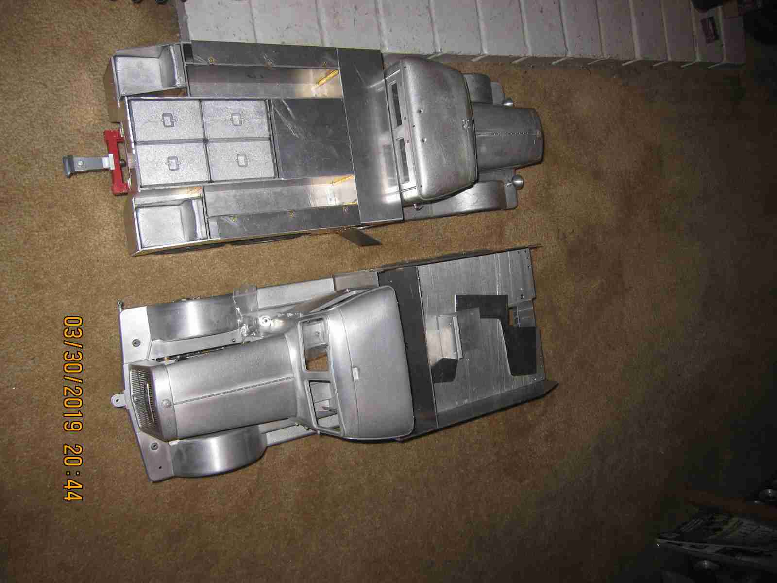
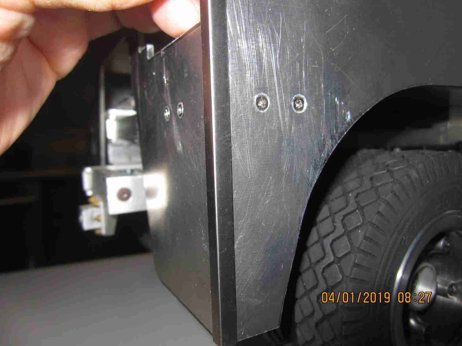
Having completed most of the body work on truck number 1 I've begun constructing the body for number 2. The first part has gone very smoothly and well however I've paused at the rear plate. When I built number 1 basically ignored the fact that due to the difference between my copies and the original plates all my joints are butt type and not tongue and groove resulting in some plates being longer by the thickness of the depth of the missing grooves. This is apparent on the rear plate mostly and leaves a small gap which for some reason didn't bother me as I thought I'll just put a short section of the brass angle as a 'cap'. Well this time it does bother me somewhat. I'm planning to shorten the bed floor plate to allow the rear plate to be mounted flush. I may, and that's a big 'may' rework the plate for truck 1 the more I look at it assuming the impact to the surrounding components is manageable. It's one of those things that makes me go 'hmmmm why did I do that, I know I could have figured that out before!'. Ah well, a senior moment if ever there was one; another way of describing something that had we done it in our youth we would have chalked it up to inexperience or impatient hastiness or lazy but in out later experienced years merely an 'oversight' brought about by temperance of years. BS - lazy is still lazy 50 years on... First things first - I'll fix truck number 2 and see how I feel. See progress below. Jerry 03/31/2019
Looking over the two body hulls I had a revelation. Sometimes it takes a while for me to see the obvious when I'm too close, standing back is one of the best remedies ever. My hulls were both the result of the way I assembled them not the way I cut the plates or lack of grooves for the T and G method of assembly. I chose to align the plates a certain way and I'm actually going forward with that choice for these two hulls. I will either use thin brass angle on the corners or I may make thin( shim stock) steel angle myself. It might raise eyebrows as not authentic but there it is. As the manufacturer of the original models called for gluing the hulls together and I've chosen stainless steel 2mm screws and aluminum angle to effect assembly I rather like the sturdiness my method provides. The addition of the angle covering the rear plate- side plate joints gives a certain level of additional strength I appreciate....I will likely extend this to also using angle caps on the assembly of the OEM hull plates if/when I assemble them. I won't be gluing them together either. Jerry 3/31/2019
The photo below is an example of what I'm intending to do. This is .005" or .010" steel shim stock cut into strips and formed into a 90 degree angle on a small bending brake. My intent is to JB weld appropriate length pieces of this on the corners when building is complete. I rather like the way these look.. Jerry
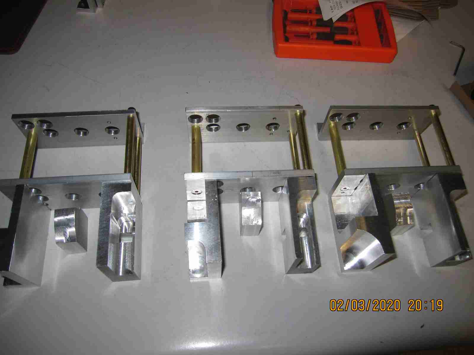
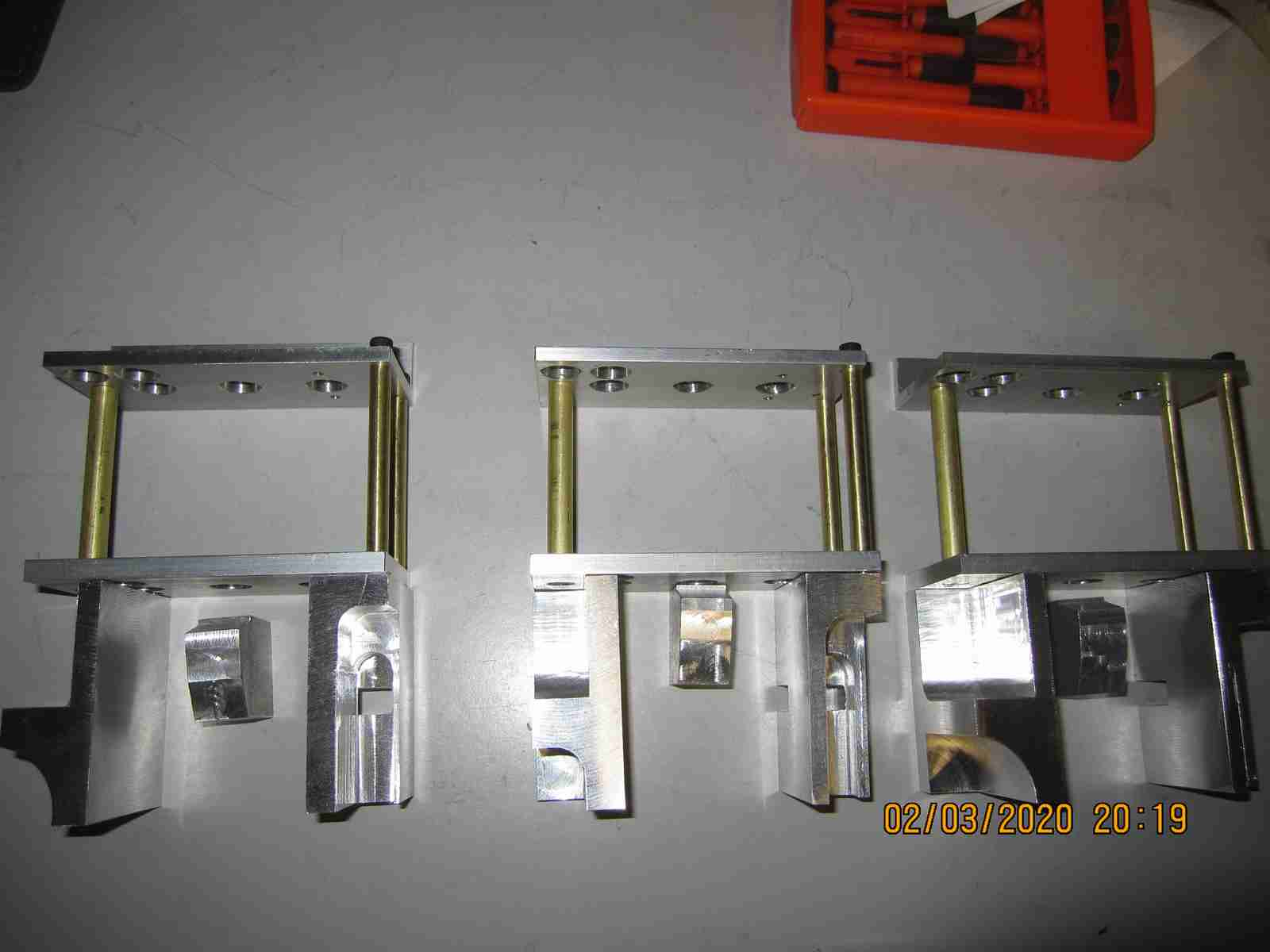
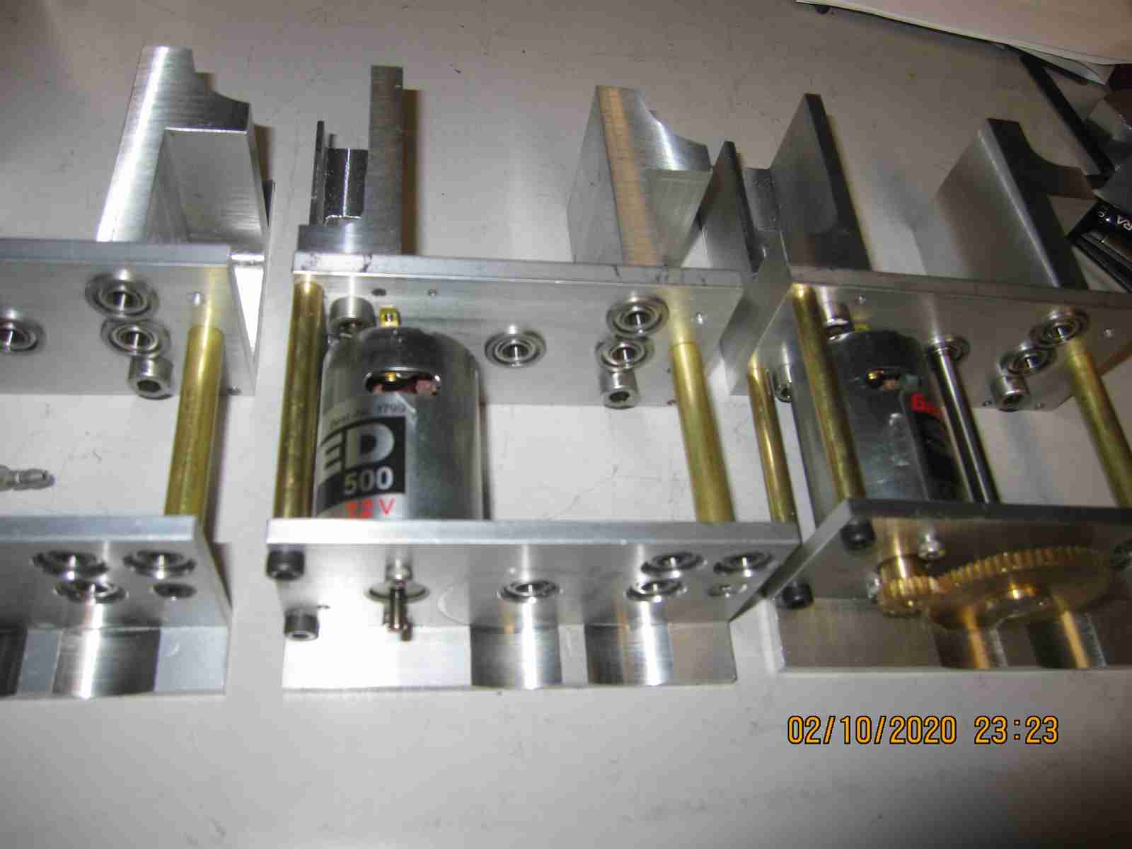
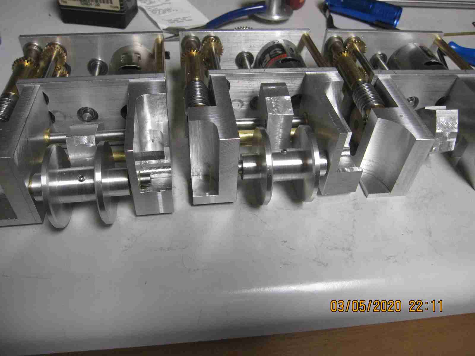
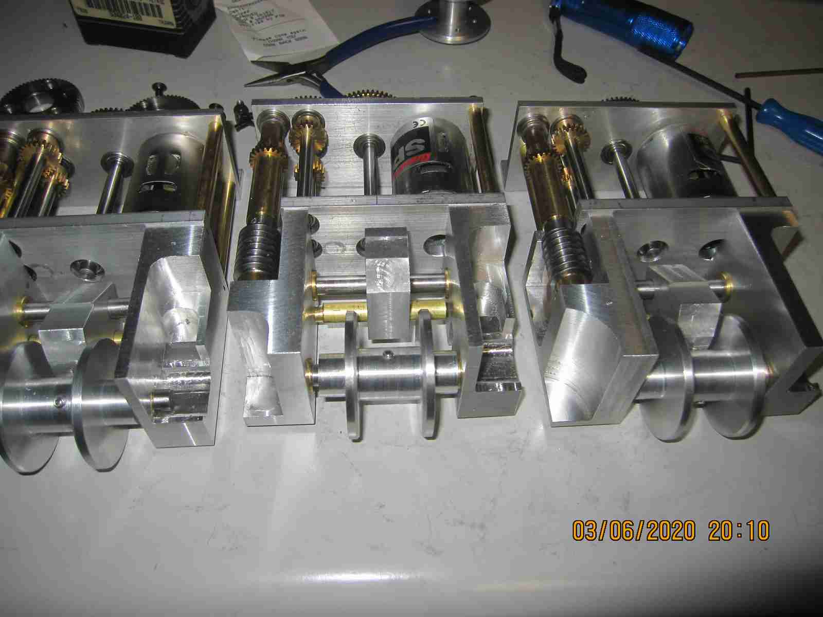
As may be seen in the photos above I've mostly finished the superstructure of truck 1 and the larger part of that for truck 2. My intention was to work out a way of making the rear axles of truck 3 actually function; as they are they are the static version with no internal 'guts'. The other item is to revisit the electric 'diesel' motor of truck 2 which I built but haven't finished. There are a few more details to be added including simulated wiring, a few 'Bosch' decals on electrical components and the 'cooling fan'; the front of the engine has a feed through power take-ff from the main power to drive the fan and 'generator' via a pulley belt. It's quite handsome. I used information I had at hand and photos from Hr Stehr's own documentation to build the unit. I took a slightly different approach with both the motors I chose and the way they are mounted however the end result should be serviceable. I include photos of it below. I'm going to finish it up then try to work out a design for the differentials.
Axles. All trucks Have some form or another. In this area I am at a loss for the terminology as to the different types. What was implemented by the manufacturer of the original models is described on their web page and in a brochure which due to any possible conflict of copyright rules I choose not to copy and display here. I should be able to reference the manufacturer's page which still fairly well reflects what is stated in the printed brochure published when Jochen Maier had first partnered with Jurgen Stehr; the brochure I'm looking at is dated 2/96 - February 1996. In this brochure there is a description of the rear axles of the model. A prominent feature stressed in words and a brief diagram is that a core element of this axle is a Zyklo-Palloid-Spiralverzahnt in other words a Spiral tooth bevel gear. The virtues of the gear are extolled, and rightfully as they are strong and quiet and very effective. Other aspects are described namely how this axle, actually both of the rear axles really have only one driven gear and not due to odd differential action but rather one have axle is not, normally, connected to the driven side whatsoever. I say normally because here is the trick: These axles are equipped with a lock, a very positive acting lock that definitively locks the free side to the driven side very securely when maximum traction is required.. There is reference to a 'so-called crossover drive' similar to what 'Büssing NAG also built this principle until the beginning of 1960'. .........OK. I got it now. I've posted a few photos of my foray into of the two axles I had Mr Stehr upgrade for me to be functional axles( they had been non-functional 'static' versions) a few years back. You may still see the description of these axles here- (https://www.stehr-modellbau.de/kaelble-z6w2a-130-c-1_8/kaelble-truck-p-1?language=de) under the section "Hinterachsen". It is only available in German but if you use Google translate you'll get the idea.
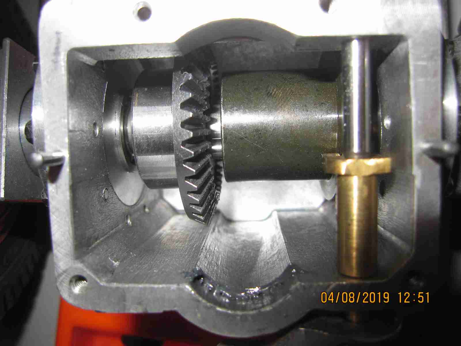

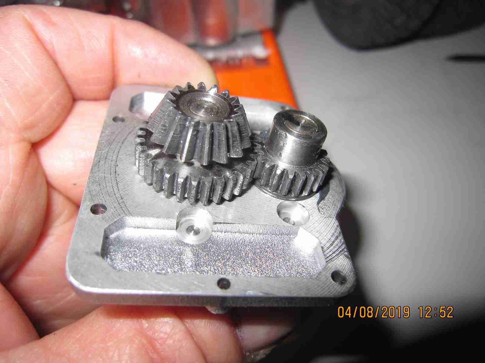
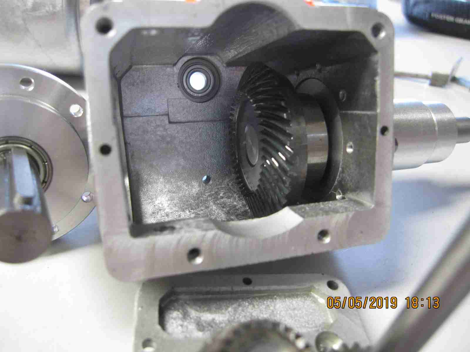
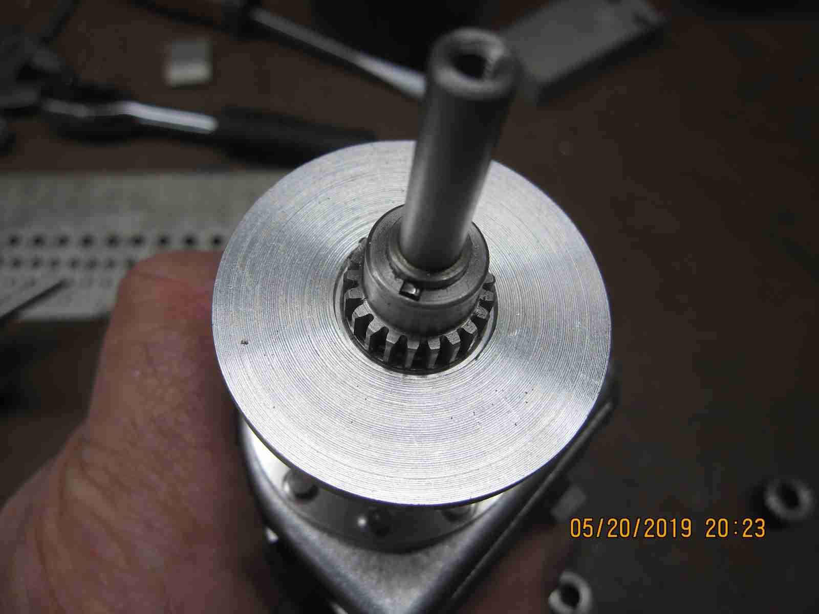
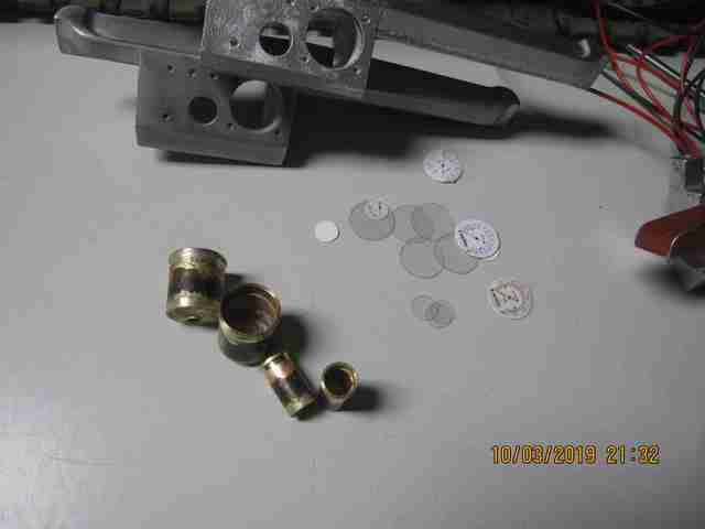
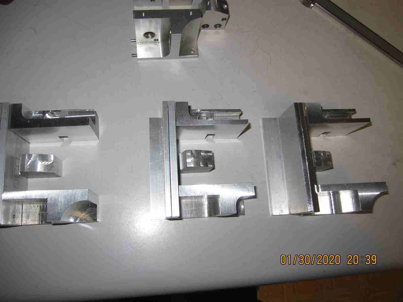
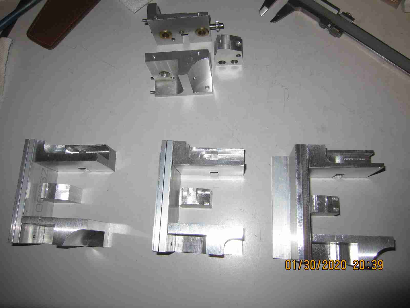
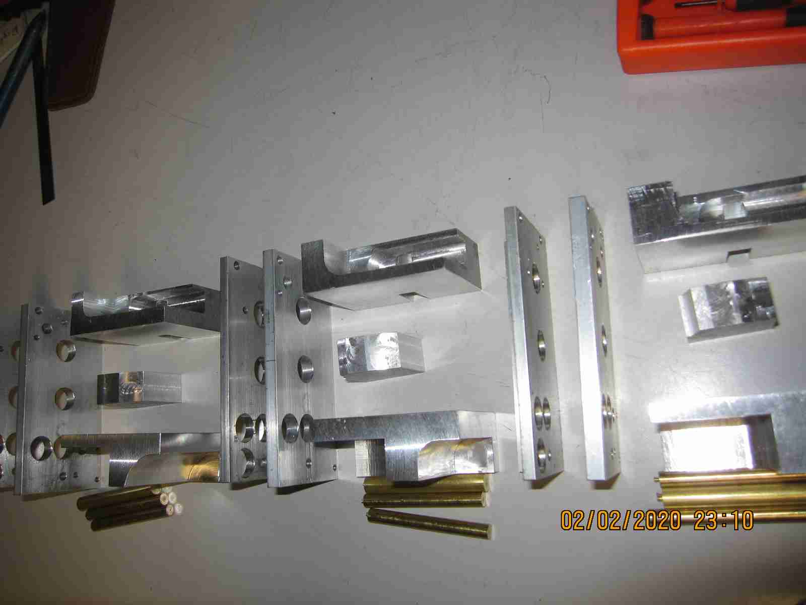
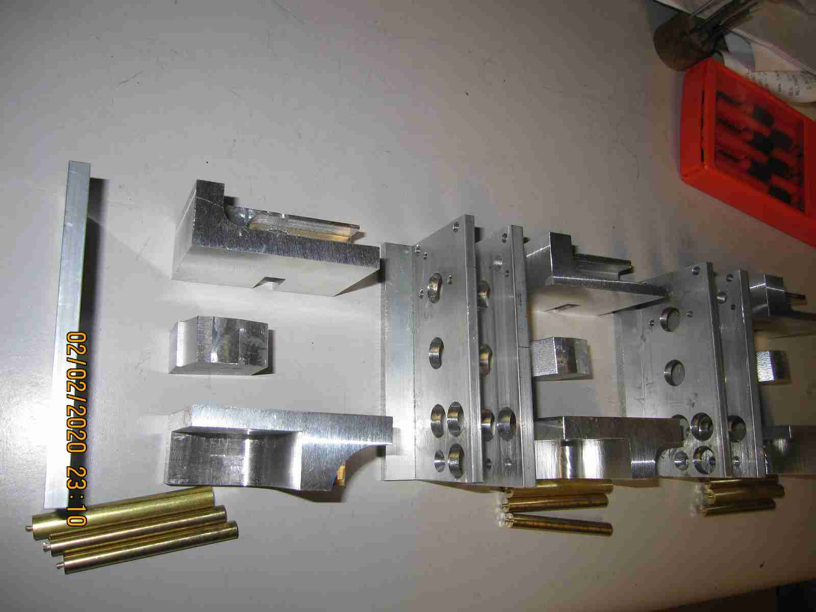
The first and most glaring observation you'll see is - where's the spiral bevel gear?? No such thing here! The bevel gear used looks very much like what you'd expect to see in any decent quality 1/8 scale R/C off road car or buggy; not a machined part. The locker is a relatively simplistic steel sliding drum with two steel pins which will engage corresponding holes on the driven bevel gear; the drum is designed to slide along a key held on the half axle shaft and is moved via a brass actuating arm on a pivoting shaft. I also realized, and I'd not been told this but the axle had been delivered bone dry, no significant lubricant was to be seen in the axle. The third image above shows the initial reduction and the cone driver to the bevel gear. All beautifully executed of course but the lack of the advertised gear was a disappointment. These Axles are decidedly NOT INEXPENSIVE! Lastly one of the two initial gears appeared very roughly cut or possibly stressed. While overall the execution as I said was well done it did leave a certain taste of lacking in some ways. So now I know how these work I want to apply this knowledge to make the axles for my third truck functional. I have included a photo of my initial experiment to this end below. I have had some beautiful spiral cut steel bevel gears for many years and I am going to see if these could be adapted. I got these many years ago when my father and I used to make weekly Saturday expeditions to ALCO Metals in San Leandro when there were mountains of diverse and wonderful things in their active scrap yard. I'd had in mind that I wanted to use these in a braked differential gearbox for a tank but as they're really too large to be practical there I'll see if I can get them to work here. I do have a backup plan as well as a second and third backup plan beyond that. These gears, having very large bores require that I make adapters which will introduce some level of inaccuracy but I will attempt to minimize that. Beyond the gearing the remainder of the axles including the planetary out drive should be simple to recreate. Jerry 04/10/2019

I've been tinkering with the two axles over the course of the last month and as always it seems there has been drama mixed in with sadness and joy outside of the play world of my modeling activities with the worst being the loss of my old girl dog Clio about a week+ back. She was a great friend and companion ( as was her sister) for me and others from 6 week old pups up to nearly 17 years, a Lab/Pit mix and a more gentle spirit you could not hope for; she is past the fear and confusion of her failing health and joins her sister who proceeded her in death by almost 3 years.
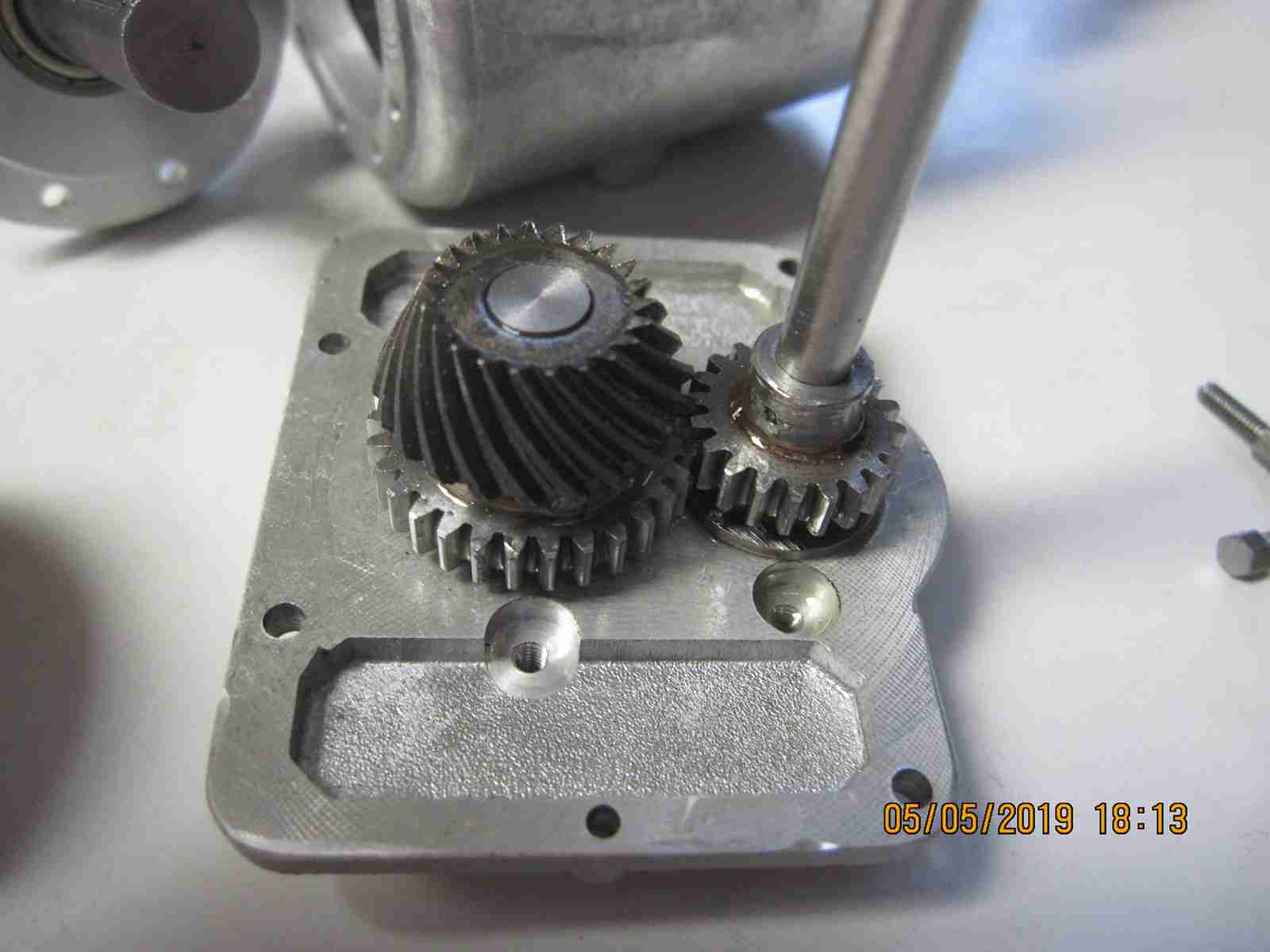
Anyway I tried several variations of bevel gears in my work to get these axles in order. First was the spiral bevel gears I had on hand but there was too much I needed to do to/with them to get them to work and when that was done they didn't run in a manner I wished. Next I purchased spiral gears for a Axial truck variation and again and more so there was too much to do to get them to work the way I wanted and the results were not satisfactory. So I broke down and purchased appropriate bevel gear pair sets from Maedler in Germany. Gads I love their stuff! And their prices to my mind are very reasonable but they always insist on DHL rocket mail and while it's great to get them in a few days it costs... Not being in the mood to write a lot (see above) I'll let the photos do the talking but this is a work in progress. You can see the bevel gears, meaty pieces, the reduction gears and the keyed sliding lock that will lock left and right half shafts on demand when finished. According to the documentation this is a mechanism in theory similar to one used by NAG-Bussing until the mid 1960s for heavy trucks. In the two rear axles only two outer wheel pairs are to be driven under normal driving conditions: the left side on one axles and the right pair on the other. Once locked all four pairs are driven. Turning must be problematic but the wheels are also to be driven by a planetary gear set in the inner hub. Jerry 5/5/2019


I've been making slow if not steady progress on the axles for my third Kaelble. They are a lot of work but in the end not THAT much. I've made the out flanges that mount the planetary( epicycle) final drive to the wheel pairs. I have one axle nearly complete as I write this. Adding the epicyclical gearing has been a challenge. The gear layout is deceptively simple in appearance but in execution, planning not so much. You'd expect the planet gears to simply be laid out at 90 degree intervals, given set gears of a given pitch, tooth count, pitch diameter and tooth angle.. You'd think that. Yet it isn't that simple. I found that the math behind working out a epicyclical isn't trivial and tooth profile standards even come into the mix. Let me say I had to fudge two aspects of my implementation. I purchased high quality gears from Maedler as may be seen and these likely worked against me in this instance... Suffice to say I have one axle completed or nearly so and I'll be happy to see this part of the work in the rear view mirror...! Jerry 05/28/2019


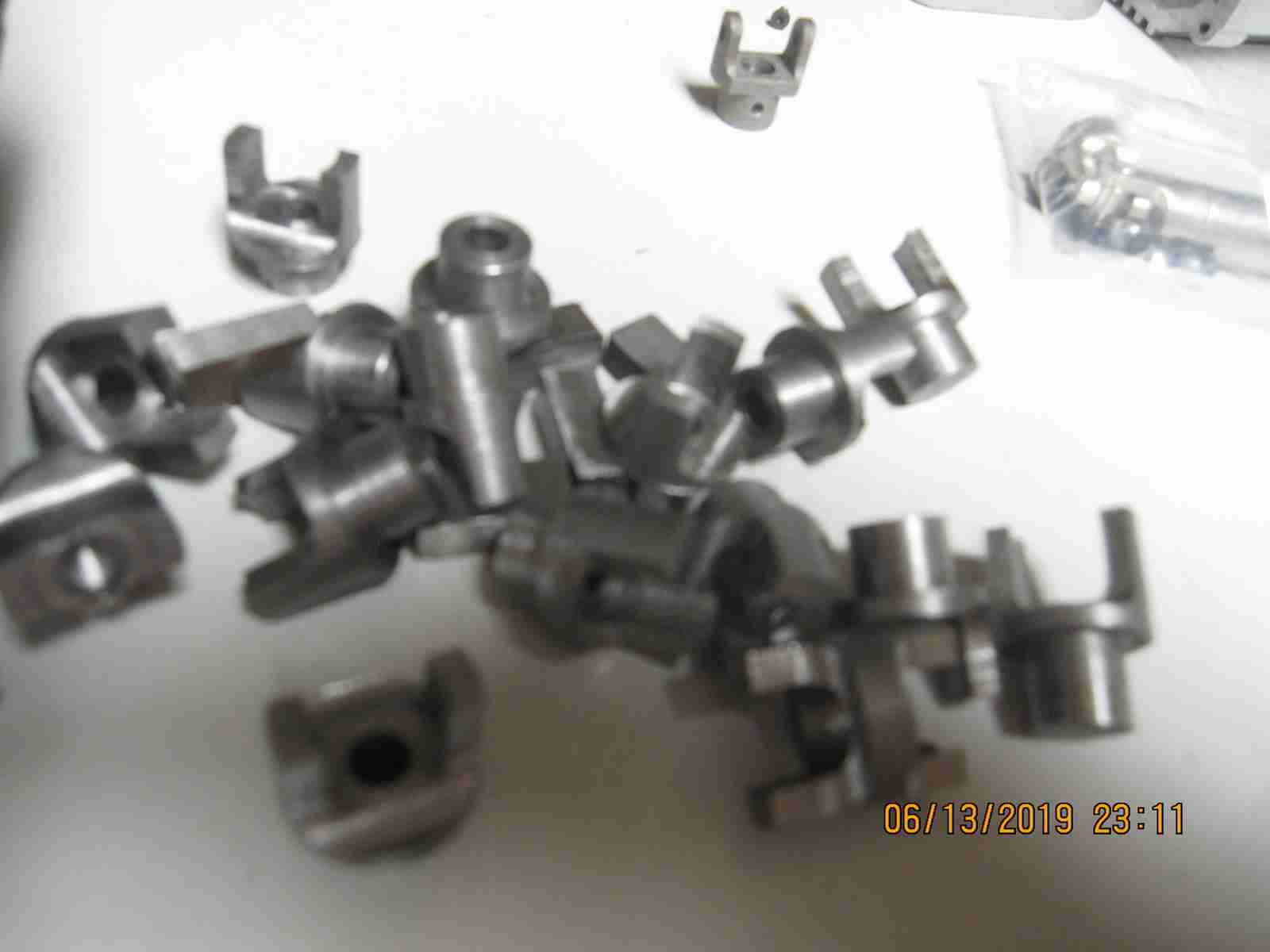
I have most of the work completed on both axles. I have to say making the planetary drives was more work than I expected and I know my implementation is not optimal but they do seem to work well. I was somewhat disappointed that even though I was careful to purchase what I thought to be identical parts to the OEM ones the fitment was extremely tight, unpleasantly so even though rudimentary calculations demonstrated that the pitch diameters, tooth counts and placement on the planet gears was correct the results were not as expected. I can only surmise some sort of different tooth geometry was used in the OEM implementation. I don't want to have to do these again! Nor determine replacements for an original.... That all vehemently laid out except for sealing the units, making the universal ( Cardan) couplings and finalizing the driven spiral gear pinning these are complete. I spent some while making the universal parts and now I'm waiting on some specialty end mills to finish these before I can finish the milling and assemble them. I found a very nicely made drive shaft made for some off road truck, I believe 1/10 scale. It is very nicely made from what appears to be stainless steel. Cleanly machined with an impressively machine spline allowing a degree of telescoping; they maker even chose to use tiny circlips to retain one of the cross pins which allows the units to be disassembled for modifications or maintenance. I'm glad I found these as it's saves me a boatload of work or at least should do. After all the hours of machine work and fitting I've done so far I feel a little guilty that I actually found an 'off the shelf' item that looks like it will work. My little Canon camera has a tough time with focus on complex parts so please excuse the blurry photos Jerry 06/13/019


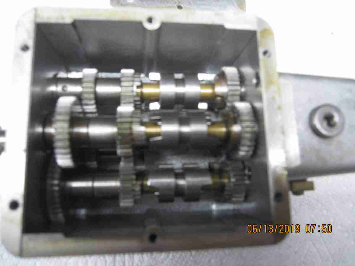
As I mentioned previously I purchased a transmission from a fellow in Germany, very good luck that was. I do believe this unit was examined by the previous owner and possibly at least partially disassembled. When I put oil in it did not hold it well. That and another thing I noticed while trying to determine how to mount this thing to the frame of the second truck is that there are no mounting holes on the gearbox body! These two factoids regarding this gearbox prompted me to want to disassemble this unit to reseal the entire AND make the required mounting holes. Also as an added bonus; since my third truck will need it's own gearbox and since I have a set of machined gearbox castings I'm thinking I might borrow some ideas to help make a simplified version to use in that truck. More to follow on this. Jerry 06/13/2019
The transmission is in pieces now on my work bench. I'm trying to decide how I want to proceed in making the third version. I see now how the thing should work but there remain questions as to why the method I see for engaging the gears was implemented as it was/is. The gears and drive dogs are cut with curious angles. As I'm no expert or even have experience with automotive or other relatively advanced gearbox designs this may well be a normal, 'standard' method. I've thought I'd use steel pins( dowel pins) and holes to effect engagement but I have to believe the method chosen was for very good reasons. I'll post photos of what I see..Jerry 06/24/2019
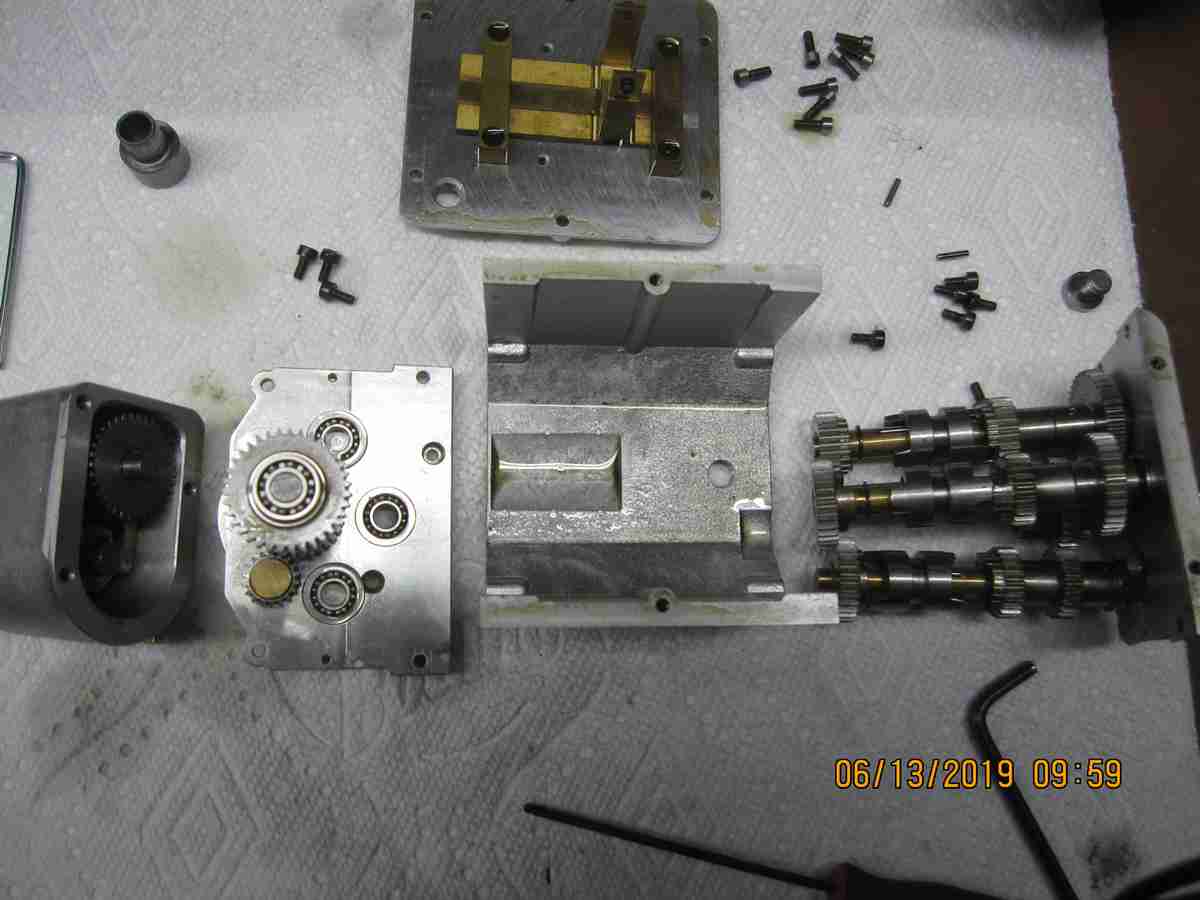
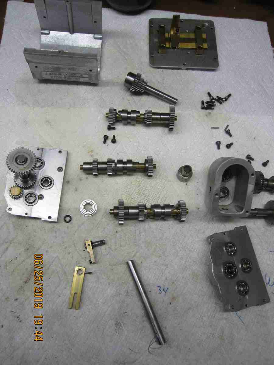
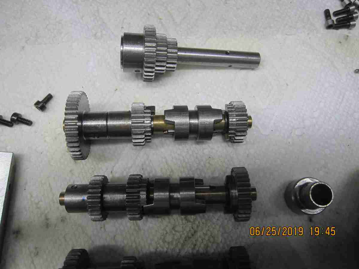
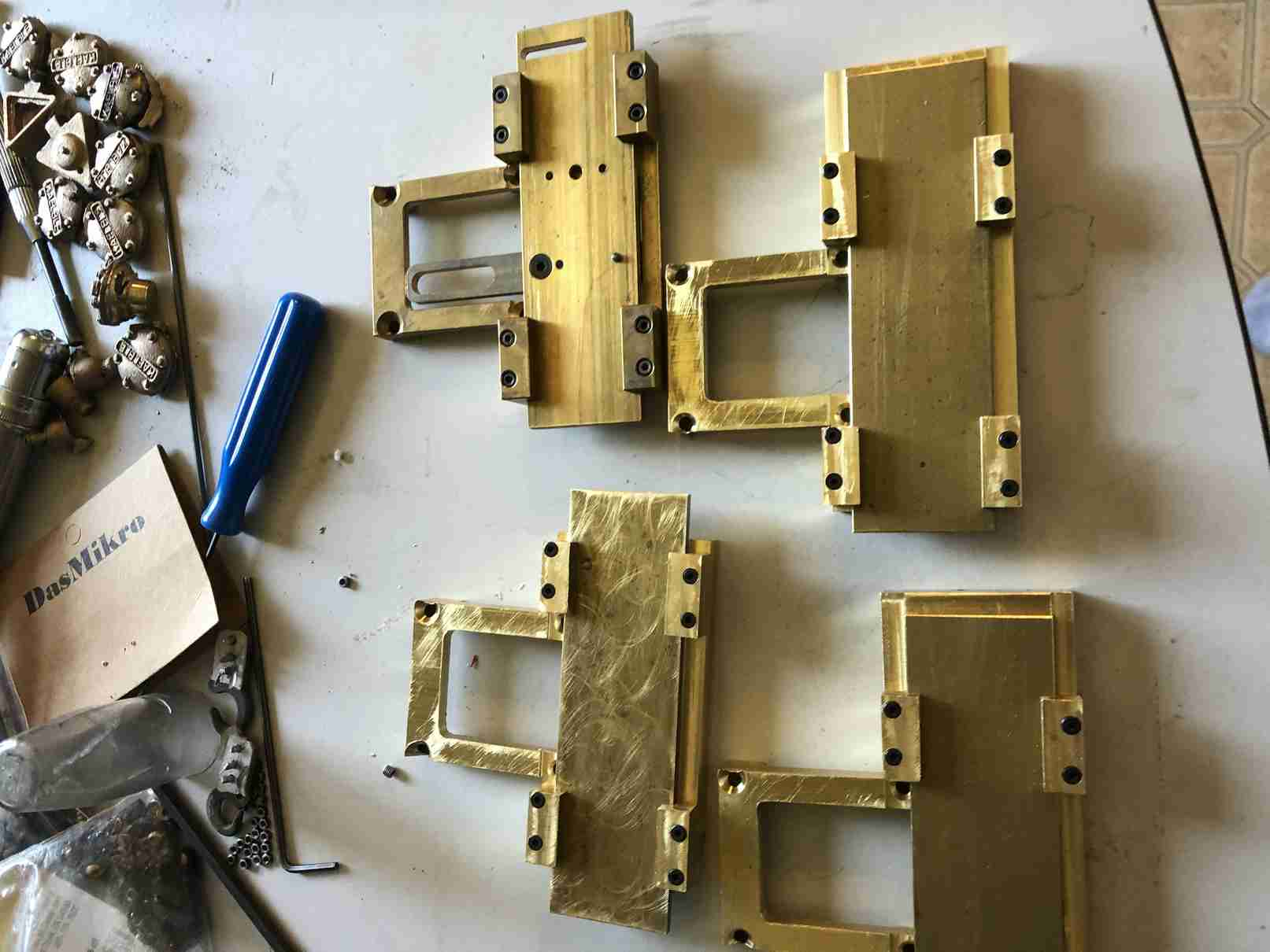
The photos below show the details of the gearbox. There are some 18 gears and some dozen ball bearings. I'd like a simpler version; I don't believe 10 speeds are really needed but in fairness I don't have any experience operating one of these models. In two of the photos you may see the gearbox housing - before and after without and with the four threaded mounting holes. Adding these was really my initial purpose for disassembling this unit; that and the fact that it leaked oil like a sieve. If you look closely at the perimeter of the top cover (or 'lid' if you prefer) you will see vestiges of the lacquer-like substance that was used to seal the unit. Before I reassemble this unit I will thoroughly clean all parts and faces and then I will reseal it as I reassemble it. I was surprised to find that the main gear clusters ride on brass shafts no doubt to minimize friction. I imagine this was simpler than making the shafts of steel and provide the movable (selectable) gears with brass or bronze bearings. More to come. Jerry 06/26/2019


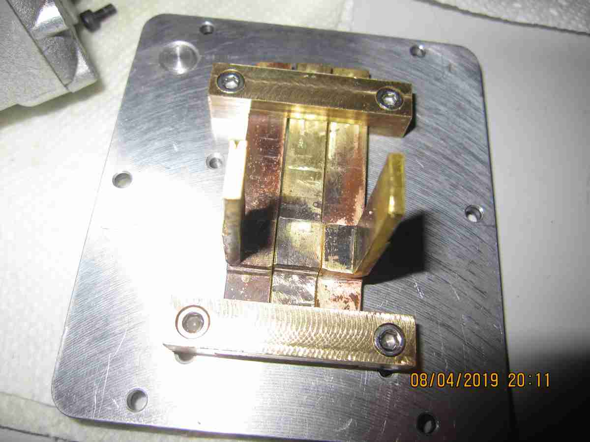
I'm going back to the rear axles to finish up some of the items that needed doing. I was awaiting 2mm end mills and 2mm hardened steel dowel-pins. I made the universal assembly that joins the two together. The axles on the right has a single 2mm spline that locks the axle input/output shaft to the universal but allows for easy removal. The left axle's input shaft has the universal pinned to it, permanently attached. I'd made a number of universal parts, enough to made 5 or six regulate unions and a couple of the double versions seen here. I didn't really need them all but is seemed silly to set up my machines just to make 2 parts. Next I need to more securely attached the larger driven spiral bevel gear to its shaft. Lastly I need to install a o-ring oil seal to prevent the locking arm shaft from leaking lubricant then seal the axle housing parts to prevent leakage. I plan to use Maier's original method of sealing using lacquer or lacquer-like material. I found silicon rubber isn't as good as you'd expect. Jerry 07/01/2019


I have adjusted the connecting universal to attach to the forward axle more securely. To assemble the two I've found it's better to connect them to the central arm assembly along with the control arms before attaching the completed assembly on the chassis. There are just too many pieces to keep aligned otherwise. I also came across an issue with the forward axle in that the input shaft was able to move forward ( it runs straight through the body) so I made a small retaining collar and implemented it and an additional bearing on the inner side to support it. This prevents any excess movement and protects the pinion gears. I did implement a large hardened pin, retained with a set screw to fully lock in the driven spiral bevel gear. I lubricated the assemblies with molybdenum grease, sealed the casings on assembly with lacquer. I tested the axles under power from a strong cordless drill and they performed perfectly including the operation of the lockers. I consider these complete. Jerry 07/07/2019
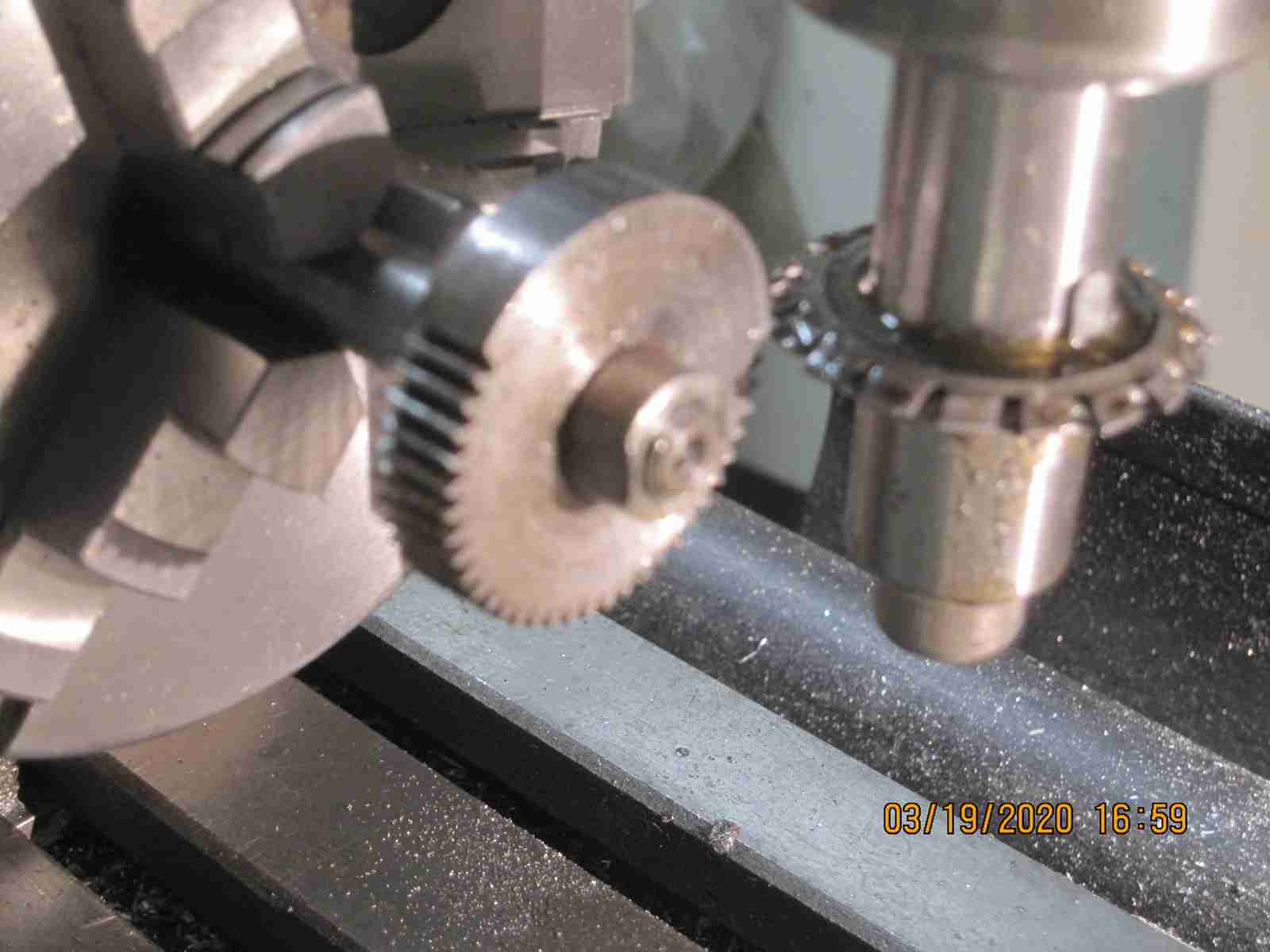
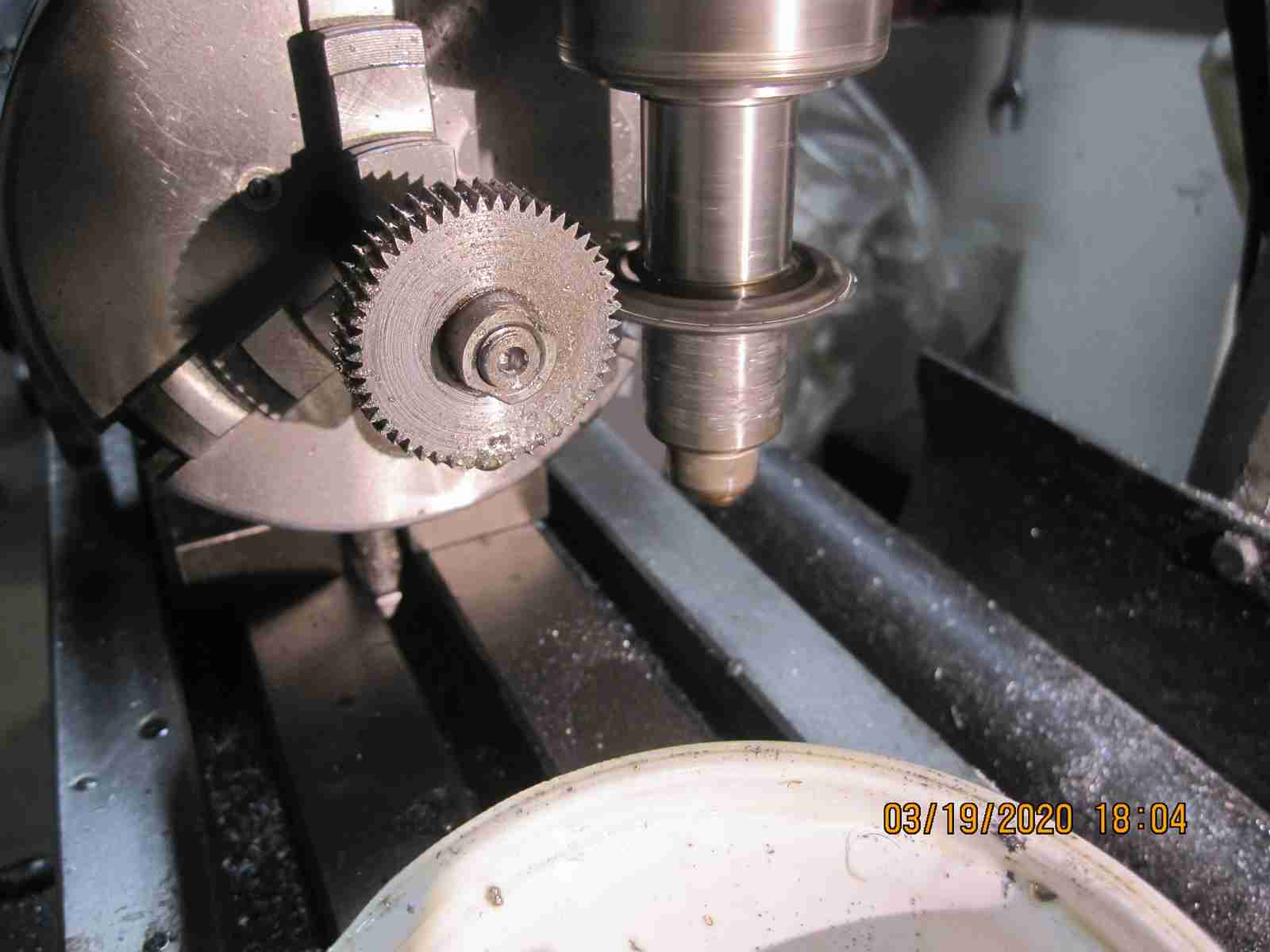
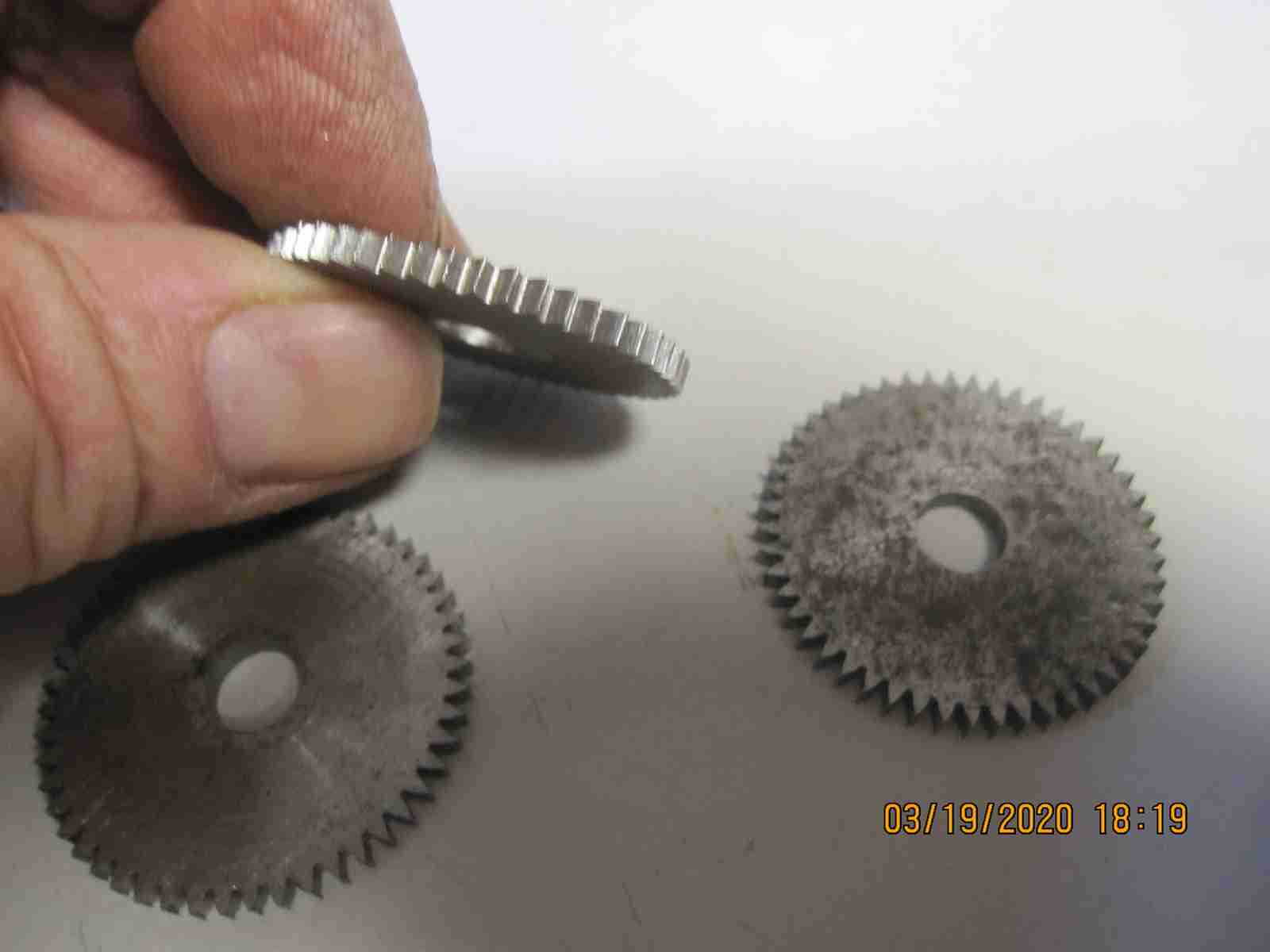
As seems to be the case more often I'm spending as much time making specialty fixtures and tool/cutter holders as actually using them. Work on the transmission for my third truck I found that I can only do so much with gears I was able to purchase from Maedler. The transmission requires 0.7 module gears and several are of a configuration I assume are 'custom' made. In order to replicate the function and since I could not find these gears anywhere I looked I needed to make these gears myself. I've had gear involute gear cutters for some while but always rather use off the shelf gears which are usually available. No such luck this time. Not having an appropriate arbor to hold the cutters of this size I needed to make one as well as a mandrel to hold the blanks.
![]()


![]()
![]()
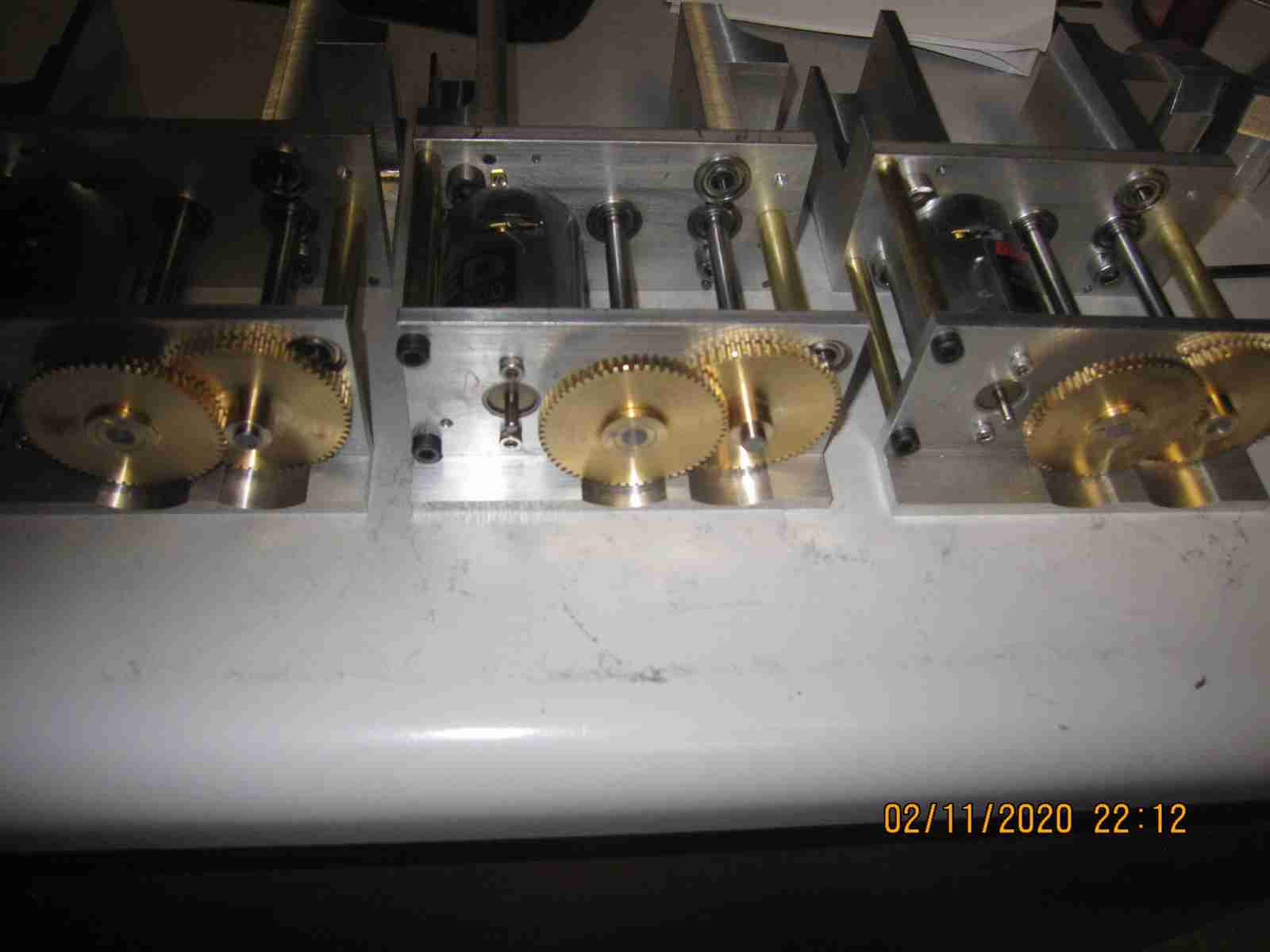
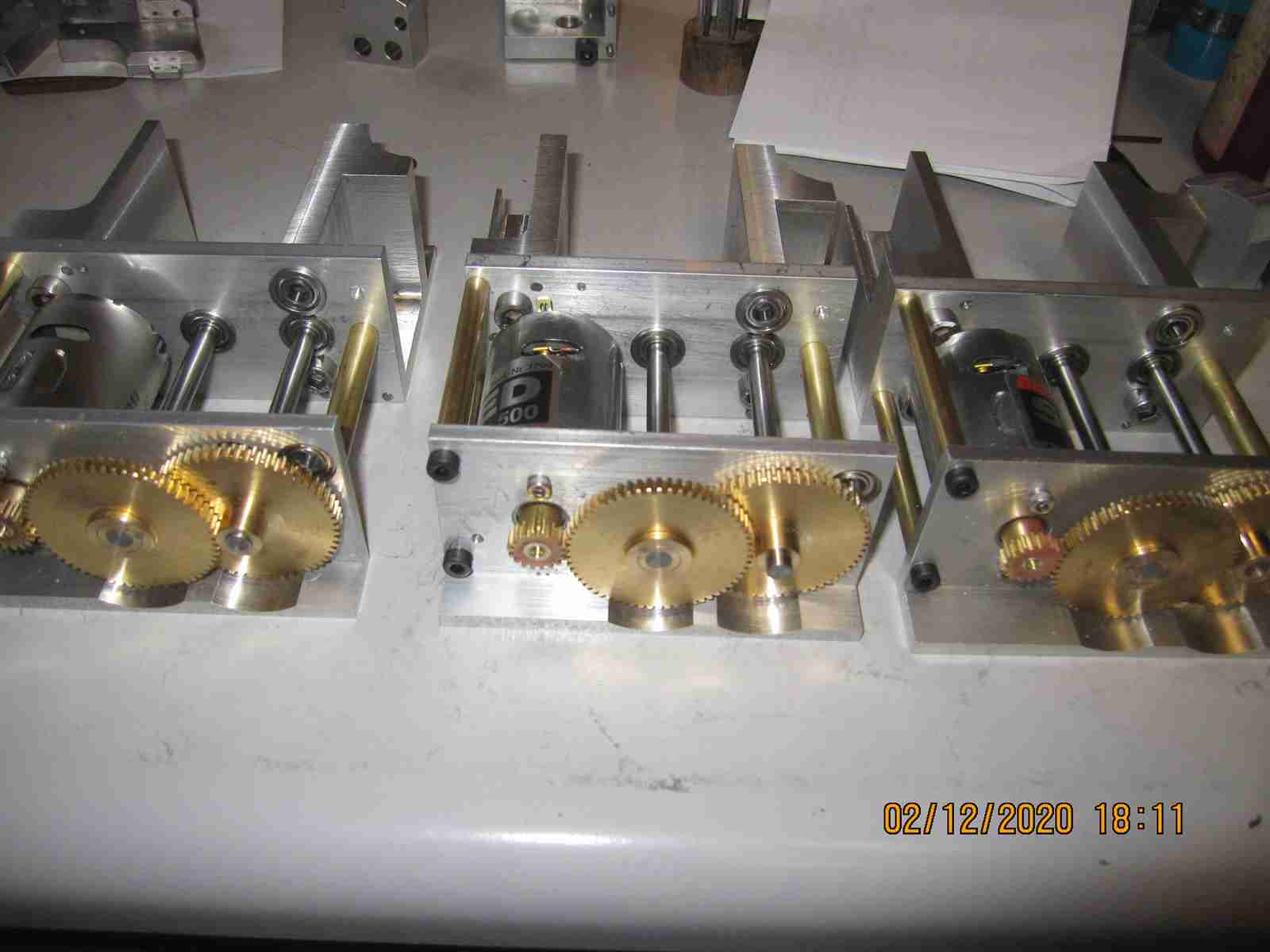
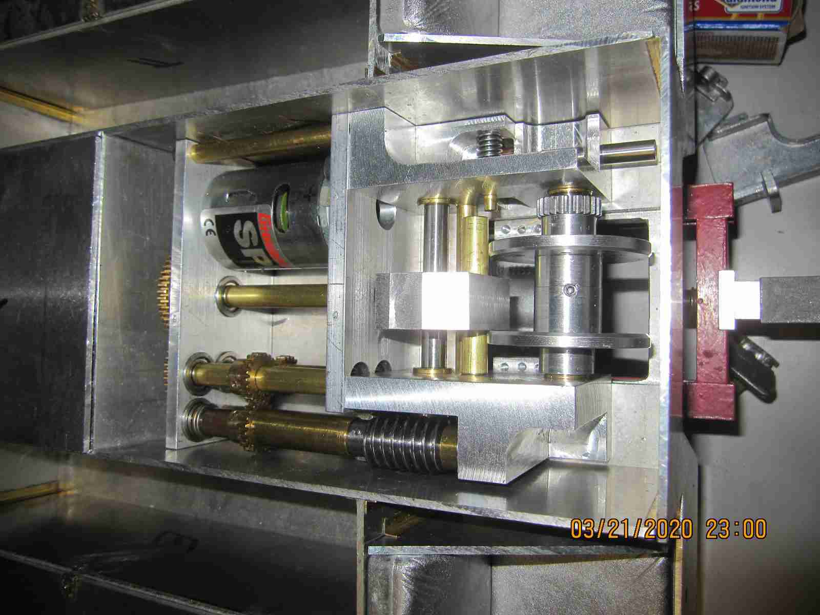
The first photo shows the gear blanks, the second horribly blurry photo shows cutting and the third the cut gears. The forth also blurry photo show the transmission in progress with three of my cut gears in the middle of the top three shafts. All the other gears are from Maedler. The last photo is just me closing up for the night putting on the Transmission cover; there is a lot of work yet to be done and I'm waiting on a tapered end mill to arrive.( to cut the selector engagement teeth).This little unit has been a lot of work but I've learned quite a bit. Jerry 07/22/2019
I've just about finished the transmission. I had to wait for some 7 degree tapered end mills to cut the drive dog engagement features on the gear selectors and gears. This wasn't terribly a lot of fun as these parts were difficult to hold while cutting. There are a few things I will want to revise at some point as the alignment of some of the gears, face to face is offset a bit and one gear I should probably remake as it is noisy. The gears on short output gear shaft are merely press fit, not pinned! I realized I didn't do this last step until after I sealed and assembled the unit. They might be slipping but I'm not certain. Fortunately it isn't so much work to disassemble and reseal. The last piece I was waiting for is the 4mm ball plungers (they look like set screws but with spring loaded balls protruding from one end) that are used to keep the gear selectors in place until you need to move one. I just implemented these this evening. I've testing the gearbox multiple times and while it's a bit still in some ways it actually appears to work reasonably well. I need to finalize a few things but still I'm going to consider this complete. I also reassembled and sealed the OEM unit I had which actually needed a modified pin on one of the internal shafts, while testing the unit this pin cam out of a gear and jammed itself in another gear which I fear suffered some damage because of it. This was not a part I had disassembled so I don't know why the pin was loose. Upon reassembly the unit seems to work as expected so hopefully that's the last of it. with the completion of my third transmission my three trucks have complete drive trains with the third truck only needing an (electric) engine to be complete mechanically. I plan to make the required drive lines to connect the rear axles to transmission for truck 2 and 3. Truck 2 already has the transmission and engine coupled together and tested together. I did have to modify the output of my self made engine to have an appropriate coupling for the transmission. I must remember that the axles of truck 2 need to be disassembled, cleaned and greased reassembled and sealed as none of this had been done by the maker. I was pleased that neither my self upgraded axles nor either transmission has leaked a drop since reassembly and sealing. Some of this latest work I've described you may see in the photos below. Jerry 08/08/2019

![]()
![]()
As you no doubt saw on the way to navigating to this page I lost one of my two little parrotlets- Oliver. This is only a few months after losing my dear Clio... Oliver was what I came to believe is a Yellow Dilute Parrotlet variety; I believe a 'breeders' breed. In his heyday he weighed 30 grams. I'm by no means an expert or very knowledgeable regarding parrotlets. Oliver is the second of his type I've been a pet parent to. The fist was Mr Beasley, I'm sure I mentioned him on these pages as well, The type doesn't appear to be long lived; Beasley died suddenly of unknown reasons at barely 8 years but I've always faulted myself for not taking care of him properly. Oliver was 9 years old but this time I took significant pains to care more properly for him; he was under the care of the finest avian veterinarians in the area and his diet was pretty good; he got exercise and I always did my best to keep him and Ivy to a 'natural' day- sun up to sun down. Oliver somehow managed to contract a type of tuberculosis. He put up a valiant fight but in the end he ran out of time. I think I did the best I could for Ollie. Oliver was a character as most Parrotlets are. He would invite himself to my breakfast especially if I was having corn flakes. He would fly and land right in the bowel and be rather upset if I shooed him off and would protest most rigorously; usually making off with a sizable flake...Oliver spent a lot of his time exploring the area around and on Ivy's cage. He was a very curious little guy, poking himself into dark areas and empty boxes if I set one out for him. When he first came to me he stayed and played with small metal bits; he enjoyed watching them fall from the table when he pushed them over. Once I introduced him to Ivy that all pretty much ended up until a few weeks before he passed. It was almost as if he was saying goodbye; he became close again; he would fly to the counter where I was working on my Kaelble and examine all manner of small bits and again enjoyed playing with his familiar metal toys as before in years past. I will miss Oliver. I can't replace Oliver but I may take in another male. Ivy has been calling incessantly since Oliver is gone and wants to be with me constantly; I can't push her away but it's not practical or safe for her to be with me everywhere. I think she needs company of her own type. I know Avian experts will argue against it likely but she really seems to miss Ollie; their cages were right next to each other essentially all their lives... So it goes. 08/30/2019 Jerry
On the Kaelble trucks- my attention has been focused elsewhere as you can see. Mechanically truck Nr 2 is mostly complete. It draws a substantial amount of power; I find I can't really test it using my desk power source. I must wire it up with a ESC and inline current/watt voltage meter to see just what it's doing. The engine draws between 2.5 - 2.8 amps just running with no load. 5-6 amps driving the transmission and 8+ amps actually driving the rear axles. Bear in mind this transmission and rear axles are factory units; all I did was seal and lubricate them. My goal right now is to build out the essential parts of the motor /engine for truck 3 so that I might test it. To this end I've already started the process. I will post photos over the next few days 08/30/2019 Jerry
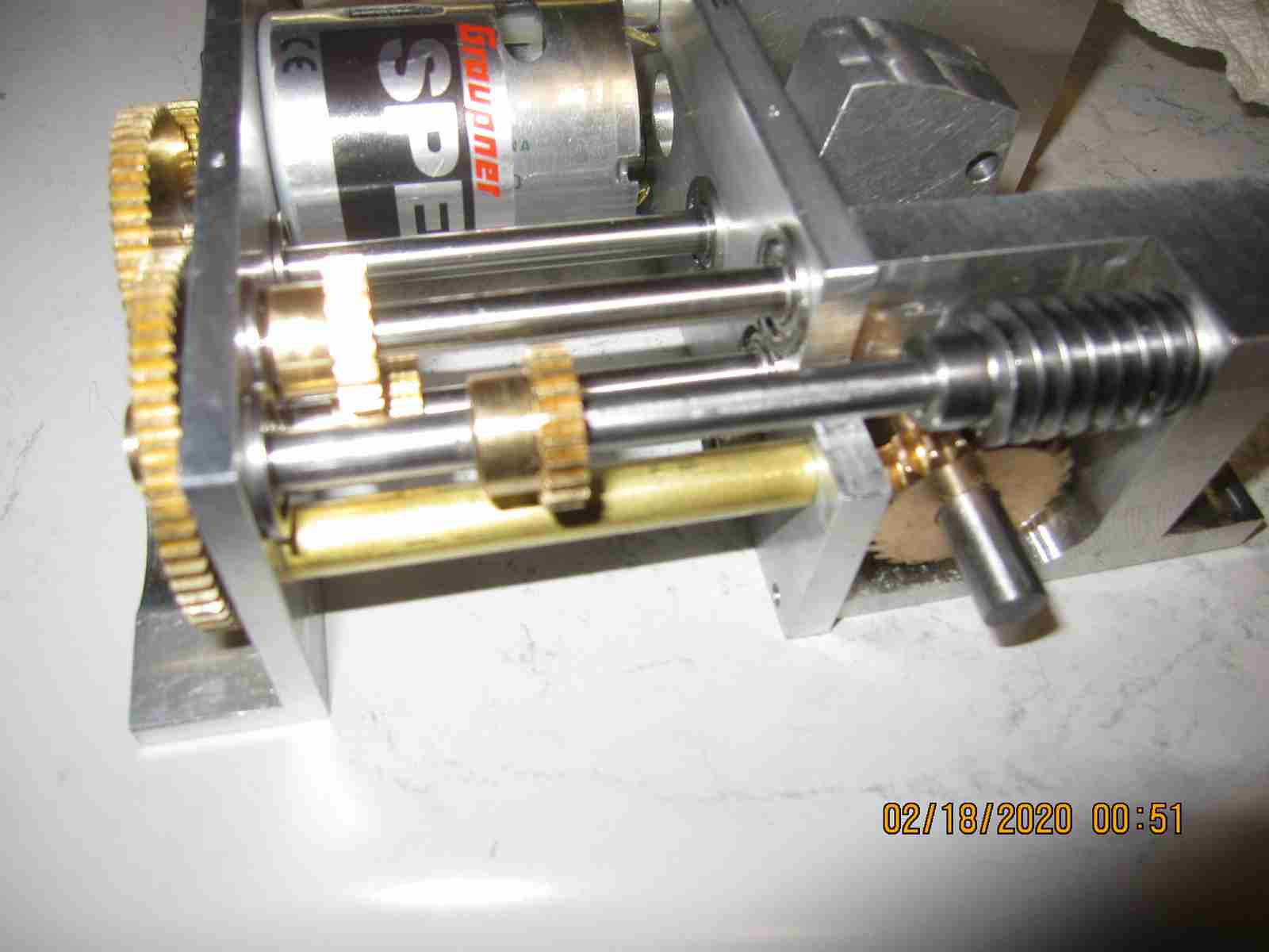
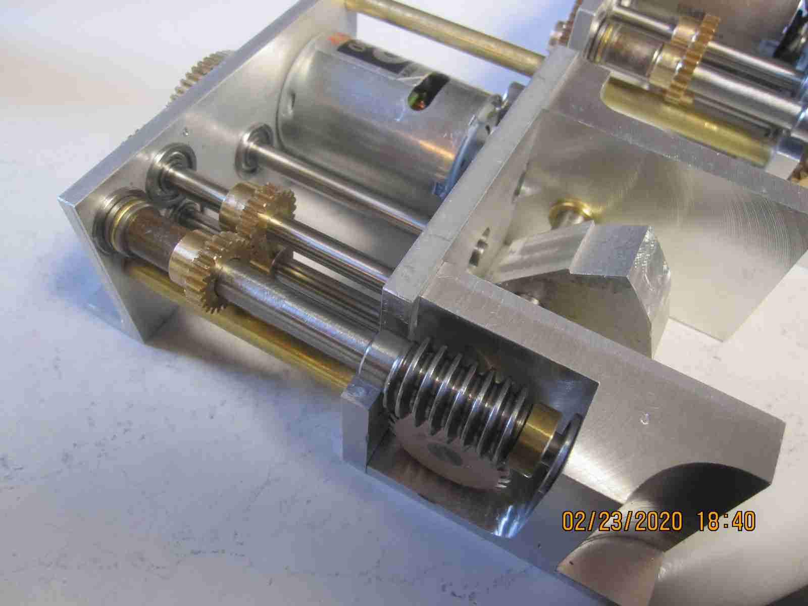
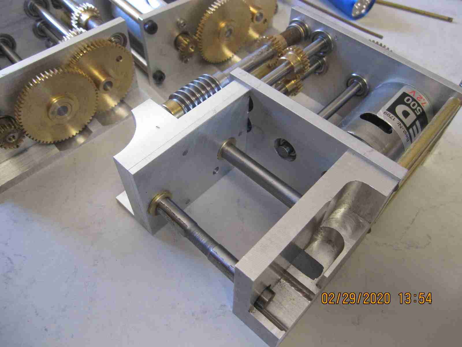
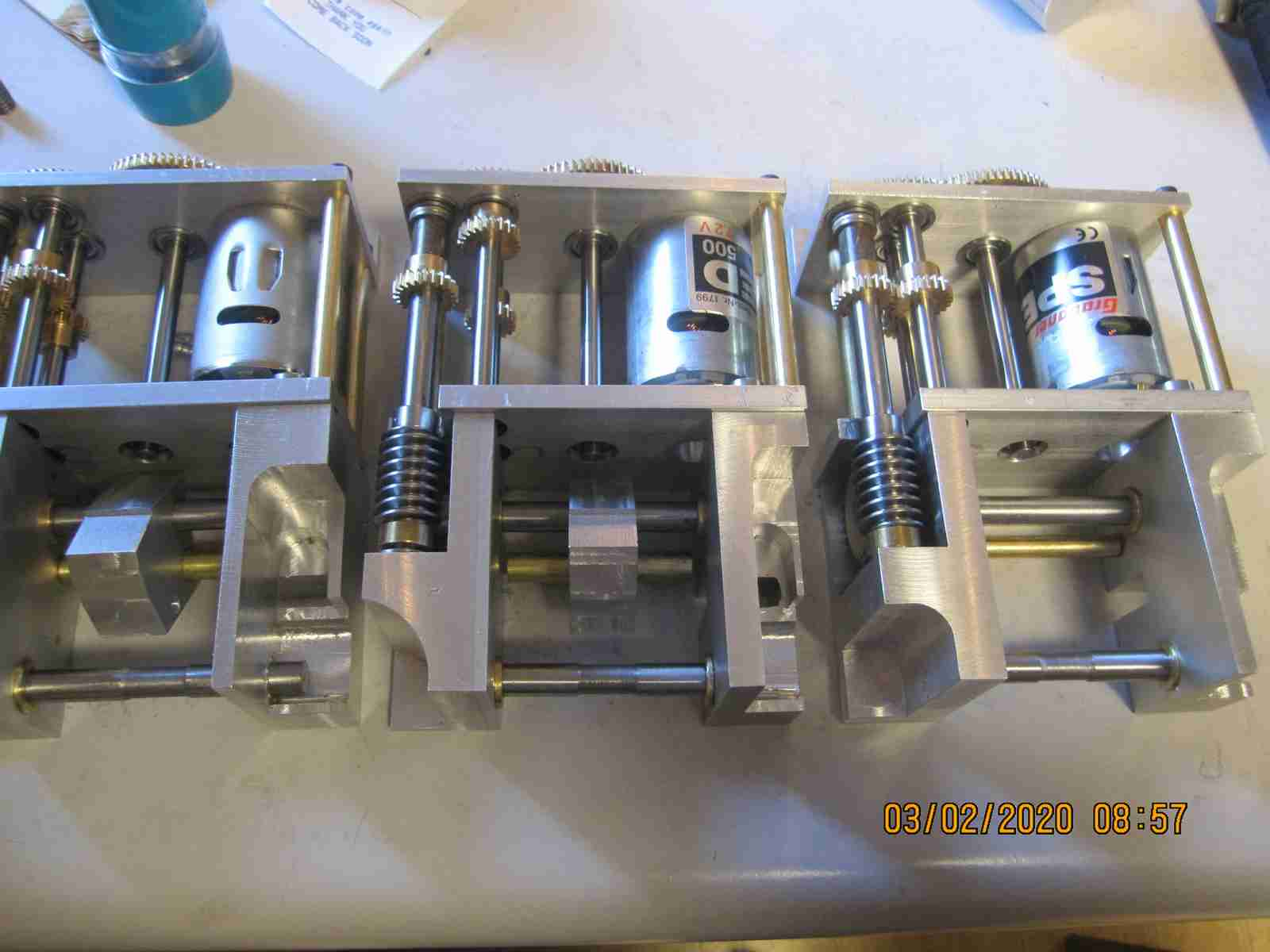
Since I wrote last I've completed the transmission for truck number three and the basic of the simulated diesel motor as well so that I could properly test the transmission and axles that I built out as described above. You'll note that the motor is complete just enough so I can run it; it has no detail parts. As you might recall, my number 2 truck seemed to draw more current than I expected using the dual 55T performance motors. With this one I used a pair of Graupner 540 "Speed 500" 7.2V motors which are basically your older type Mabuchi 540. When running this test I also employed an inline power meter. I'm pleased with these results, it worked even better than I'd hoped and power use, as a no load test was very favorable topping out at about 7.5 amps with transmission/ transmission over drive and axle lockers all engaged as may be seen ( if you look carefully) in the latter portion of this video. There is much to do on all three of these trucks and even though these three represent a lot of work it's really just scratching the surface; that said the work of the machining and mechanics are complete for all three. Now all that remains mechanically of note is the rear mounted winch and that's not immediately required for operation. Final decision as to the three trucks configuration and other details will be the fun part. Obviously I have to finish the motor, the drive shaft between transmission and axles needs work, I'll like make another as I did for truck 2 and all three trucks will need details, radio gear and all that jazz. axles. From a drive train perspective mechanically all three trucks are complete but there remains a great deal of work on these. I will likely, as I always do when my projects reach a personal goal milestone semi-sort-of set to the side. I will work on all my projects as the mood strikes. I want to focus on my long standing Tiger II project, more about that later. That's all for the moment Jerry 09/17/2019

![]()
Kaelble truck 3 video, integration test of both rear axles, lockers engaged, transmission (3rd gear) and functional but incomplete diesel motor as described above.
Taking a break from all the machine work and working with the dashboards of two of the trucks. I've not yet found a photo of a dash of a full size truck so I'm purely just using imagination. Photo documentation on these trucks is scarce even in the Kaelble specific book I have: a few outside shots and that's it. In fact considering Kaelble built a few hundred of these machines for the German Army it's difficult imagine more photos weren't taken. I suppose perhaps the fact that they aren't as high profile as Tigers, Panthers and other all the other highly studied military hardware of the day contributes to the slim pickings for information. Anyway I've tried a few things using small, 3mm LEDs for lighting and photos of vehicle instruments I've massaged into the correct size. Below is a in progress first attempt at one dashboard. Apologies in advance for the poor quality of the lit-up dash photo... Jerry 09/25/2019


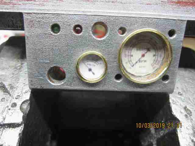
Continued to work on the dash boards for these trucks. I changed my approach. Instead of simply trying to use enlarged holes in the dash itself to build up a representation of instruments I decided to bore out the two instrument stations and make separate 'instruments' to fit in these positions. Two sizes of housings were built from K and S brass tubing and silver soldered together. Dial faces were printed and punched out as well as thin plastic 'lenses'. The housings were drilled for a 5mm warm white LED. I made three sets for the three trucks. I like the way they've turned out. There's a few other things I need to do and I should be able to wrap these up shortly. Jerry 10/03/2019
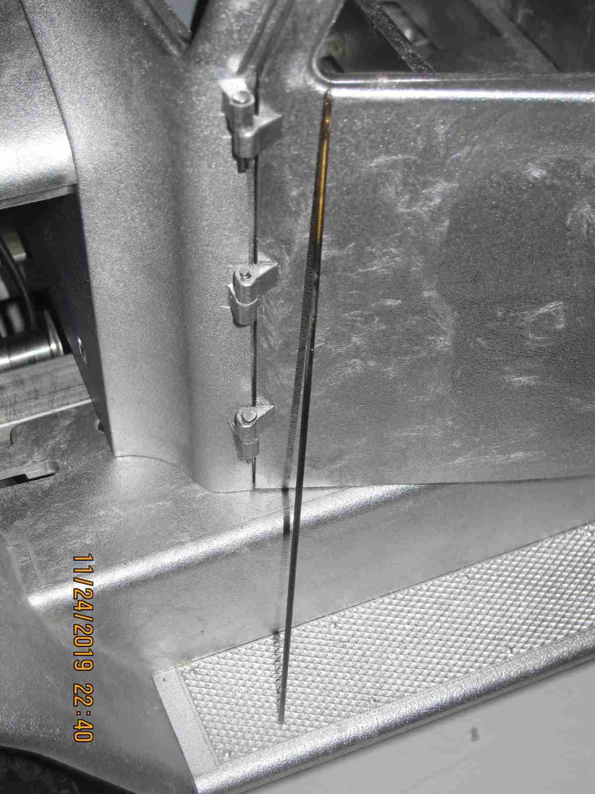
I've spent some time on the front body work and cabin of the third truck. Assembling the cabin took some while and machining of the base plate as they didn't fit together very well. I hadn't had this much work assembling the cabin body on the first of the two formerly static trucks although I don't know how much work the previous owner had already done in terms of fitting the castings. I also realized just how much I dislike drilling the pin holes for the cabin door hinges. There's a certain amount of pressure not to screw these up since the hinge points are integral projections of the castings. It's tedious work and awkward. For the first truck I struggled making the holes on my drill press until I silver brazed a number 54 drill onto a steel piano wire to make a really long tiny drill. In the photos below I show a door with hinge pins installed. That's all for tonight! Jerry 11/24/2019

I've not actually been sitting still on this project over the last month. The body work I described above is just a bit of diversion, albeit necessary diversion, while I gather more information on another component of the complete truck system. As this comes together I will post the progress of this, the last major mechanical component of these trucks. Where once I thought I might make the third truck as a late-war simplified flatbed / stake bed type now I'm not so sure. I will likely build it out as the others. More to come.. Jerry 11/24/2019
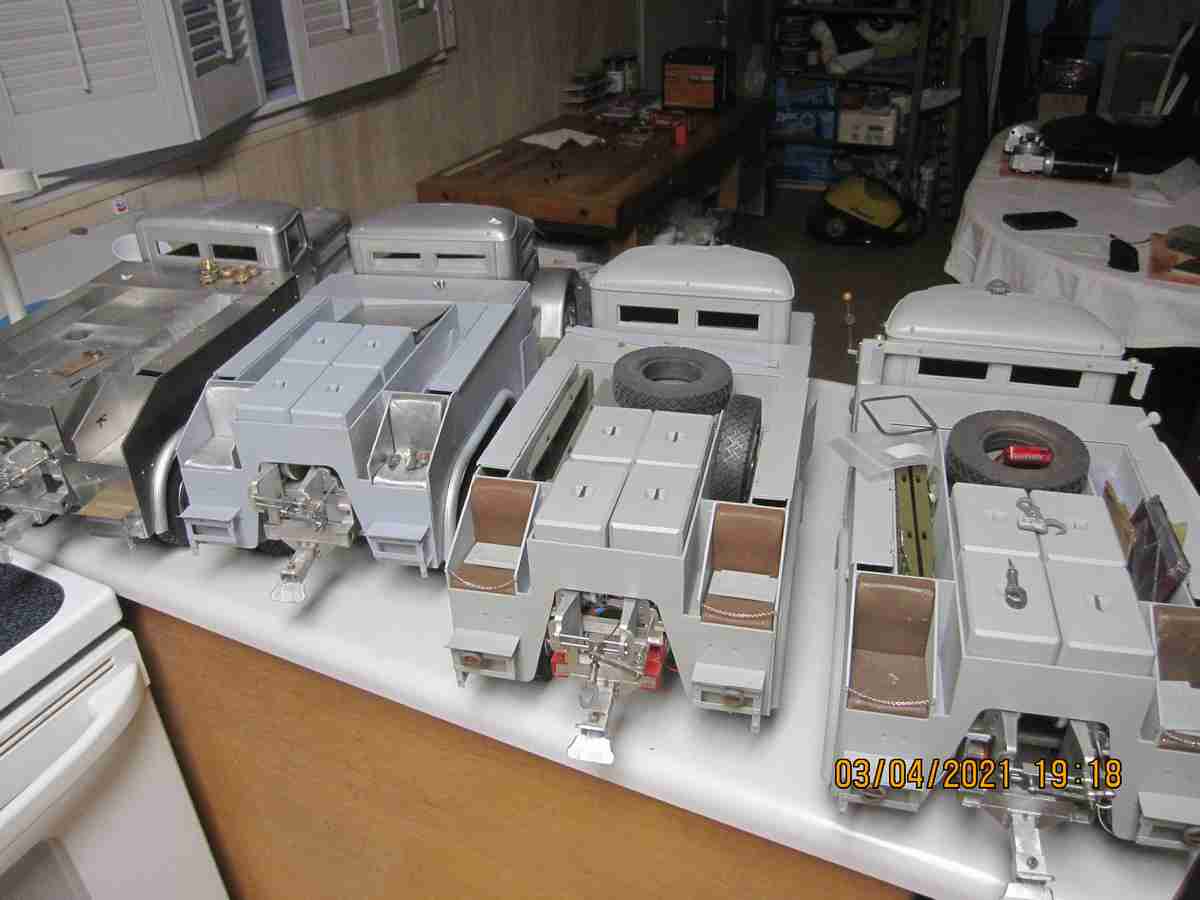
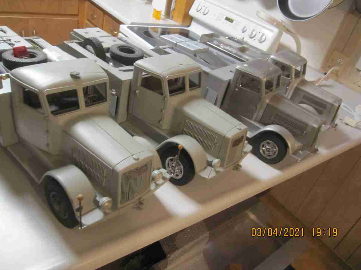
Below is the trio as they appear right at this moment..I did decide to go a little wild with the color I used to paint the diesel engine in this third model! What the heck I found a beautiful blue and couldn't resist using it...as always I'll blame the deviation on a late war small sub contractor who didn't get the color memo...!!
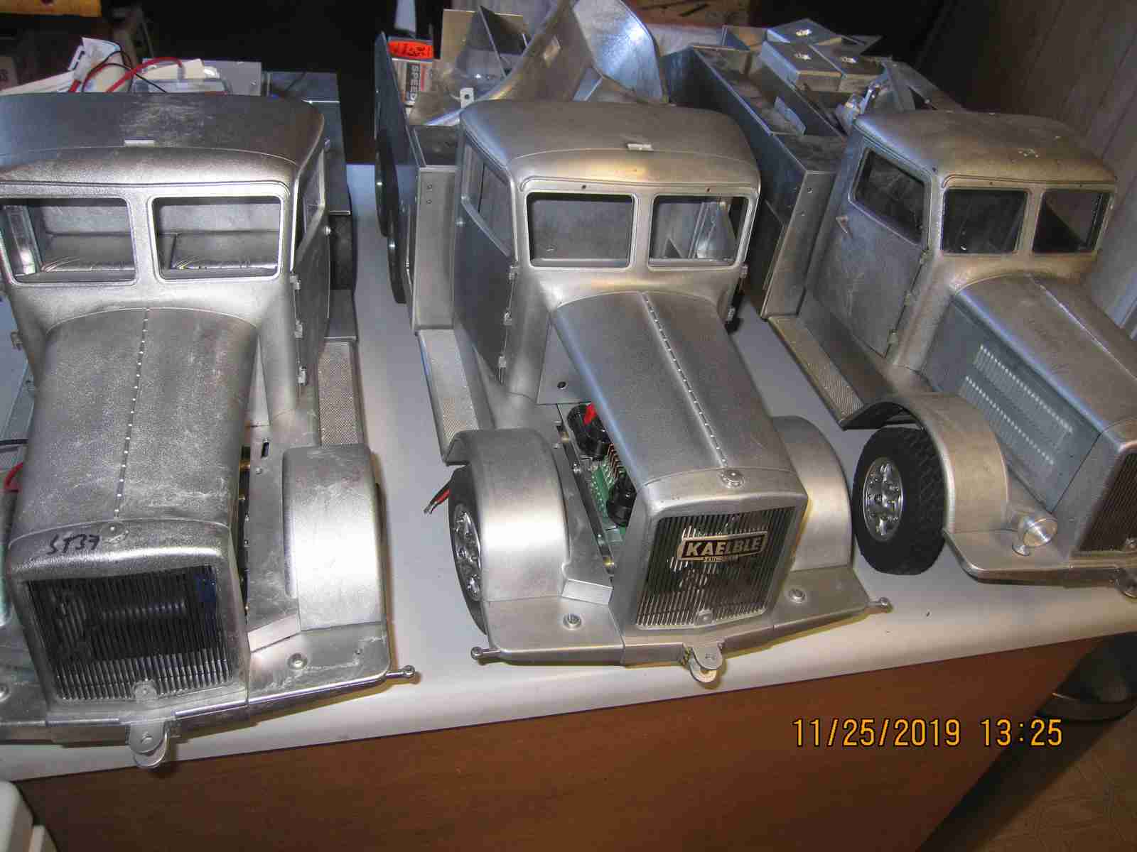

A fourth Kaelble Z6W2A 130
Yes, that's right. I purchased a fourth Kaelble!! I'd been discussing this model with the owner, who I won't name here, for well over a year. I finally got going and paid for it and it arrived. Therein lies a story. It is a very early version of this model; according to the previous owner one produced when Jochen Maier still owned his business. If I recall it, this example of the Kaelble was sold around 1994-95 which is 1) earlier than I thought he began selling them and 2) before I reconnected with Jochen after moving here in 1990. Like many people I use landmark events, (in this case moving to this home was a pretty significant event!) to organize the chronology of other events of varying significance and I recall reconnecting with Jochen around 1995 perhaps later in 1994 but I could possibly be in error. I do know that in 1996 I visited Jochen and his wife Irene and stayed with them for a week before staying at a Hotel in Munich. Anyway I digress. The model is mechanically much different than the later examples I have detailed above yet does have basic mechanical similarities. The model has a single huge Bosch electric motor for power. The transmission is a 5 speed with some sort of cylindrical unit in front of the gear case whose function I cannot fathom. It has a actuator arm which barely moves and seems to do nothing. Inside, pinned to the input shaft is some sort of flywheel that presses up against a stiff spring but does seems to either disengage or engage anything. I did remove the gear case cover and it is very similar to the later style units however it uses steel pins (dowels?) to effect gear selection instead of the elaborate angled mating surfaces of the later style. I did note that the gear case is equipped with steel shaft rods and not brass as the current units. Examining the gear case only made the mystery of the other unit more pronounced as I could see nothing that seemed to be effected by anything done by the aforementioned cylindrical unit. It doesn't seem like Maier's MO to just put something on a model or mechanical unit that serves no purpose. I have photos of this thing below and anyone reading this knows what this is for please, please let me know! Now for the rest of the story of this model!
As I mentioned this is a complete model, an early example of the truck and one of the aspects was that it was sold complete with Lowboy, the Gotha Type 80! The truck also was equipped with the winch which is a piece of equipment I sorely wanted for my other three trucks. I discovered that the previous owner decided not to use the gear selector function so he had locked the gearbox in the first gear and left it that way. Also the locking rear axles were always in the locked mode as he also had set them in that mode; he used screws in the control of the transmission and the axles to keep them in one position. I plan to make these both function assuming I am able. His implementation of the model's function was using just one servo for steering and one speed control each for the main power and winch. I'll keep this going forward. He has a sound system and control for lights. Again I'll keep this going forward but as his radio system was an older German 40 MHz system I cannot use it here in the US, it was never legal here, I will use a new 2.4Ghz system as the basic control. I hope his other units will function as they seem to have Futaba compatible J plugs.
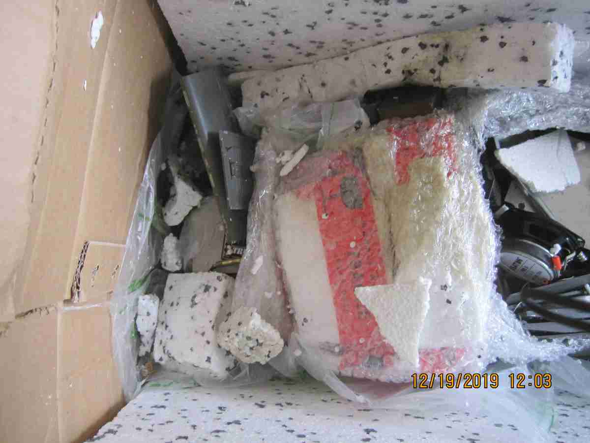
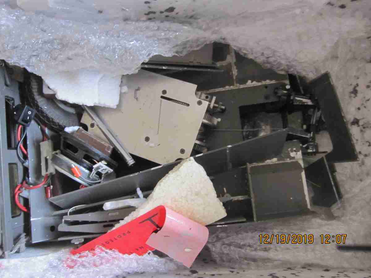
And now for the downside to all this. In short the model was severely damaged in transit. I will not point fingers. The damage was extensive with the truck although largely easily repaired however requiring a lot of work; the lowboy (sent separately) was less extensive yet annoying nonetheless and as of this writing largely repaired. The worst of the damage to the truck is that one door hinge point was cracked along the axis of the hinge hole- this will be the greatest challenge to repair. Most everything else was the result of shifting of the model and components impacting one another in transit- mostly parts becoming unglued. This highlights my only exception with Jochen Maier's models. Even as far back as his Panther A models he intended his kits and basic models to be able to be built by people with minimum or no mechanical skills and relied upon gluing most of the metal parts to each other. This something that ultimately will not stand up to time not rigorous use (or abuse in this case). I will detail the state of things later and my cleaning and repair. To look at this in a positive light it affords me 1) the opportunity to familiarize myself with a very early version of this model system and 2) allows me to 'build' it using my own methods. That I paid for a complete model and really didn't get it IS annoying on a fundamental level but knowing that I love to bring order to Chaos there is peace in that.... One last thing: it gives me the one piece I was missing and the ability to replicate it- the winch and cable laying mechanism.... Jerry 12/27/2019
Below are photos of this model from the time I received it until now. Jerry 01/16/2020


Below are photos of the transmission and motor of this model, cleaned..
![]()

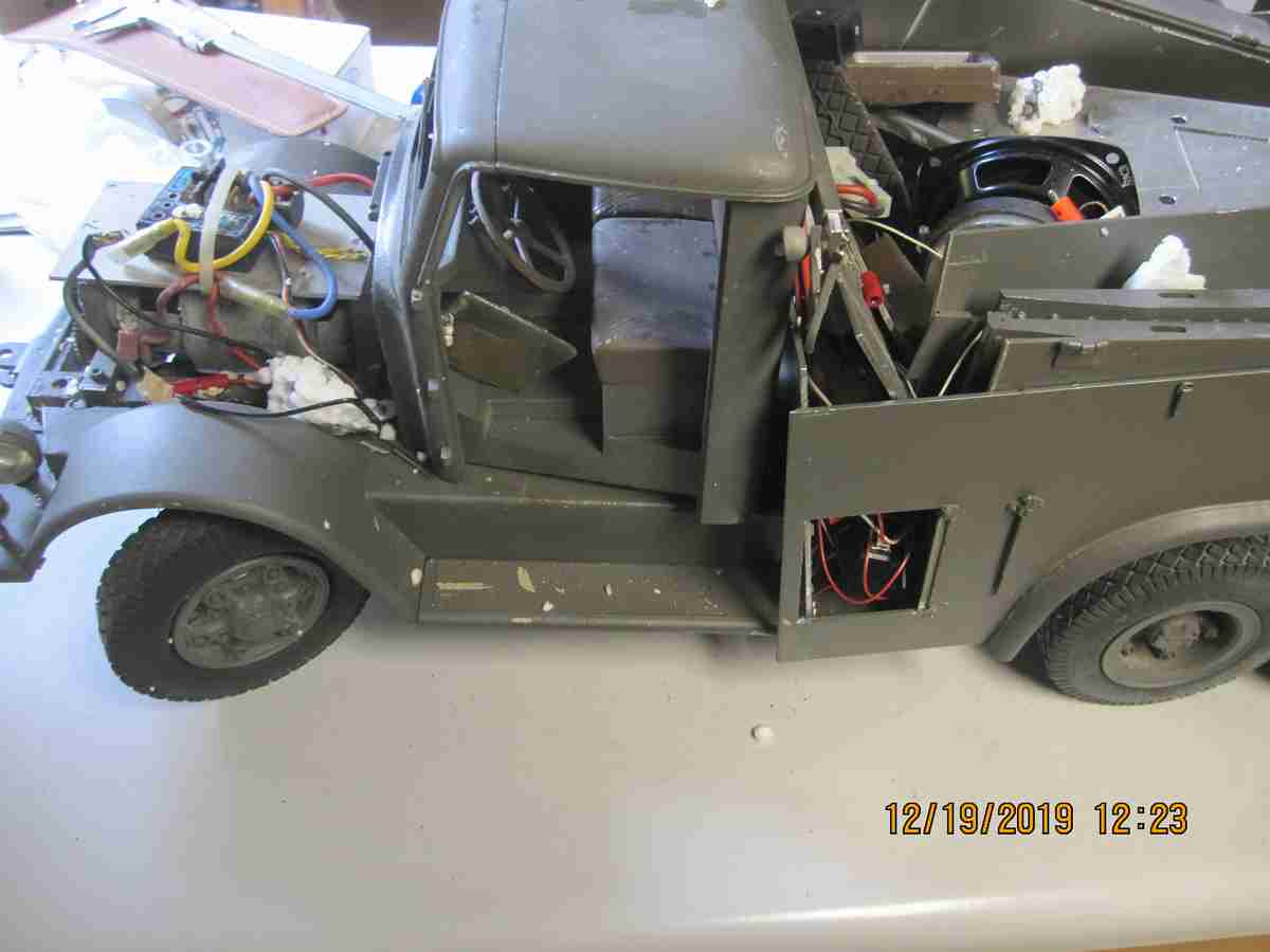
Below are photos of this model as it appears cleaned and most repairs completed.

Most of the repairs on the Kaelble4 are complete, at least the most time consuming ones, rebuilding the rear body work, repairing the left door hinge. I found that the cab assembly really didn't fit well in relation to the front grill and hood after I reassembled all of it. There was a stripped thread on the grill which I repaired, once all front cab, hood, side panels and cab were cleaned and repaired I found they really didn't fit together well on the frame so I took some time to properly align these parts and now they go together well as may be seen. Plus not being a fan of glued metal to metal parts I have replaced as many as practical with traditional fasteners and I remade several broken lead parts with steel or brass versions and there are several more things of that sort to do. I refastened the cab to the frame similar to the way the other three were done. I'm going to wait to do the other details of the truck so I can prepare the other three in the same fashion then paint all of them at once. I purchased special color paint from Klasscote which should be very close to how this one was painted, a color I like as it is late 1930s - early war years. I hope to add a certain level of detail that I haven't yet seen on any of these. I just received the gears which should hopefully allow me to equip all the trucks with a functional winch. It will be a fair amount of work! I will post highlights of this effort. I do want to ultimately get these trucks as fully equipped as I am able. I may sell one or even 2 of them. Together with the Gotha type 80 lowboy they are a very large model and heavy but very unusual and interesting.
A winch, my kingdom for a winch.
Please forgive the whimsical, silly sub heading. As odd as it may seem one of the reasons I agreed to purchase the 4th truck is, it being as complete a model of this type I'm ever likely to own, albeit an old version it came with the rather complex yet mechanically exquisite electrically powered winch. I've coveted one of these since I've known about the model. From my point of view this one accessory elevated the model, already a wonderful mechanical marvel to a level far above the common 'RC Truck'. The winch is powerful, purposeful and in my assessment adds a level of complexity I enjoy.
I originally enquired about purchasing one of these when I received my first truck, the non functional display model. When I sent away the axles to be reworked into functional ones I asked about the possibility of purchased both the 10 speed transmission and the winch. I was told that it was unknown when either of these two units would be made. On top of that the price I found for the winch was extraordinary, such that I will not even quote it here. Fast forward to receiving my fourth truck in the exploded state shown above. Fortunately to the best of my ability to determine the winch itself was not damaged however the outboard cable spooling mechanism was somewhat damaged, broken. I repaired that damage and part of the repairs to the truck required fully removing the winch; in truth it hadn't appeared to be properly fastened to the truck bed in any event.
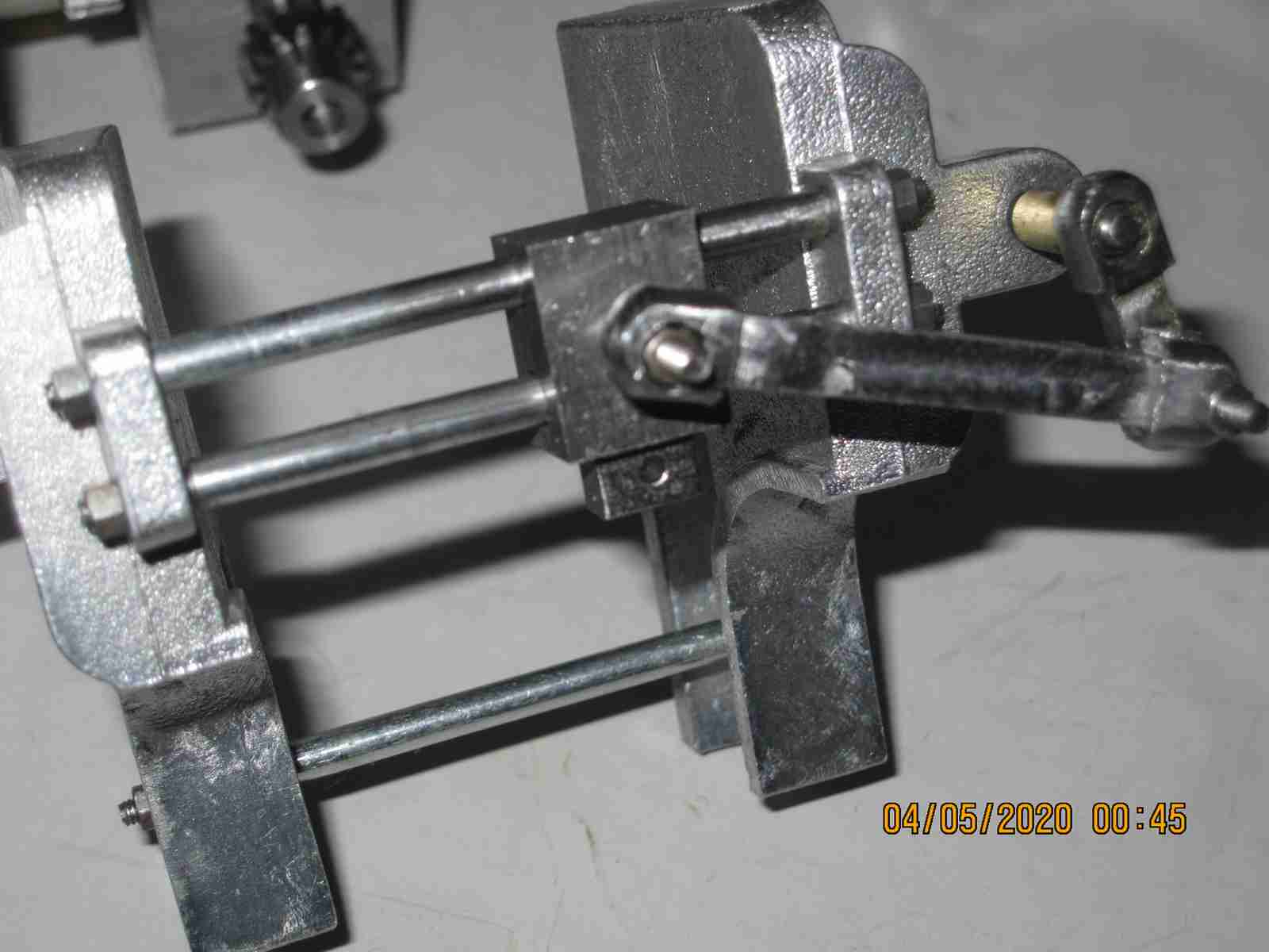
I examined that winch from every angle. Prior to receiving the fourth truck I had used photos of the winch sent to me by the seller and the owner of another truck which had the winch to make approximations of how the mechanics and dimensions of the winch were laid out. Having had built up a truck body I had a real tangible approximations of maximum dimensions for the height, width and length of the unit, Using the photos I had and these dimensions I began to make the initial reduction gearing and frame for my own version of this winch, seen in the photo below- without motor- removed for future work

Enter an original winch with my fourth truck... WHile my estimated dimensions were actually quite close to the 'real thing' I learned much about the details and running nature of the actual winch. At this time I decided to make my own winches based on the original; I decided to make 3 since I had 3 trucks that need them. The photo just below shows an example of an original( with outrigger cable 'spooling' mechanism) but is not mine.. I am sure there is a proper name for the cable spooling mechanism but it's job to ensure the cable is placed back on the drum evenly...

So in these last few months I've not been sitting on my hands. I've been doing a substantial about of machine work. As I write this I am waiting for additional components that I needed to special order. I've done just about everything I can do except for fitting the power take-off used to run the worm gear driven cable spooler. There are a few small shafts and gear assemblies to make but the greatest challenge remaining is this small worm gear set placement. I will likely need to make additional components to fit these/ In total the winch has 21 gears. I will lay out the progression of these three units in photos below; not including the very first steps of preparing the aluminum blocks used in the winch body.


There is still much work to be done on these units. As I mentioned above many parts need yet to be made, final pinning of gears to shafts , spacers, fitting of the final gearing, making and assembling the cable laying mechanism components and brackets; finally the overall fitting, testing of these units. These things represent an enormous amount of work, much of which is quite tedious and dare I say it: stretches both my skills and the accuracy of my machines. I have given serious consideration of leaving out the cable layers altogether and I do not rule out that major parts may need reworking or actual replacement. I don't usually post things before final completion but there it is. Jerry 03/06/2020/
Here's a brief test video of the small worm drive used for the spooling mechanism. Nothing is pinned together yet and the clearance between the gears is a little looser than I'd like but for now I'm going to move forward with it as is. If this implementation becomes problematic my fallback plan is to make separate bearings from brass bar that I can reposition as needed to adjust the backlash. Setting up worm drives has always been a challenge for me and the configuration of this unit makes it more difficult especially considering what I have to work with. If I were to need to do more of these it would be an excellent case for CAD and CNC machining... Jerry -3/12/2010
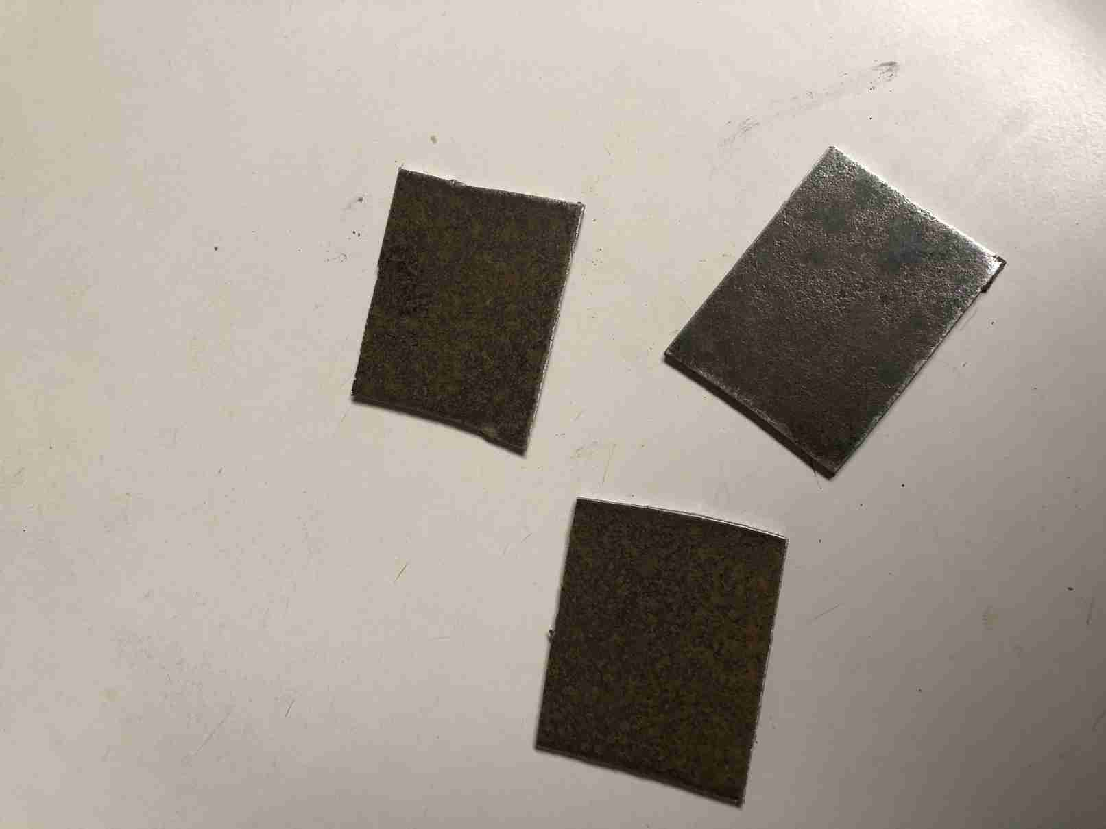
Well as of a few days ago, today being 03/20/2020 everyone in my area was told to shelter in place because of the spread of the horrific COVID-19- "Corona virus". Other than not having the option of enjoying the occasional breakfast, lunch or dinner out my routine hasn't changed much. The greatest change is not going over to the Hornet where I volunteer 2 days each week. So I have more than enough time to work on modeling projects. To that end I'd decided that for a particular gear I need for the winch construction I didn't want to hack the beautiful gears I'd purchased from Maedler. I decided to cut my own. They needed to be thin, about .100" and so I made them from a scrap piece of mild steel I found in my shed. It's time consuming, tedious and boring work but I'm stuck here anyway so why not. A few photos below show this work.
I'm doing some odds and ends tasks on the three winches. I have to finish the small worm gear drive, fixing the gears, for the cable spooling mechanism. One of the three is going to be a little problematic as I'd made one of the cuts for the worm wheel too deep; this was due to the overall height of the part- I hadn't checked it to see that it was too tall. By the time I machined it to the proper height I'd already made the one cut to deep seriously removing material from a place where there's very little excess. Once I realized this I was already committed and decided to see how it works as is. Alternatives are to a) fabricate a partial bearing block and mechanically fasten it in or to b) make a new block altogether. I'd choose b if nothing else works. so once the gear drives are resolved its basically making the mounting holes on the base, machining the entire case of each unit to get to a uniform level plane so the covers, also yet to be made, will fit properly. Other that it's wiring the motors and then waiting until my special order gears arrive and final fitting. I thoroughly cleaned and reassembled the original example winch. I was fiddling around with this and my three units fitting one into my number 2 truck just to check the fit and I also remounted the original winch into number 4 truck; I left off the cover so I can check fit on my other three units. I also remounted the spooling mechanism. Jerry 03/21/2010

I haven't run the original winch much but while doing so I noticed a problem with the outboard spooling mechanism. It has an series of small arms that move a cable guide back and forth in front of the cable reel. while this seems ok in operation the drive shaft that engages the output drive from the winch is free to move and there's nothing to prevent it migrating back towards the winch and if this happened the shorter of the two arms will bind on the longer one. As I can't see that there a sacrificial pin anywhere this will likely be a destructive event. My plan is to make a spacer that will go on the outboard drive shaft preventing it from moving backwards..I think also going forwards this mechanism, while very appealing to me seems vulnerable and I think I'm going to try to work out someway of preventing it from damaging itself if it were to jam; first thing that comes to mind is a soft pin somewhere that's easy to replace if called on to fail or perhaps some type of mechanical clutch that slips if too much torque is applied... Stay tuned.

I've made the last parts for the 3 winches including the outboard cable laying mechanisms. I assembled 2 of those mechanisms as that all the castings I had; at least the original castings; for the last unit I need to make my own castings and prepare them however I made all the other parts needed. This thing is a fun mechanism to watch- the oscillating arm assembly particularly satisfying. The three winches themselves are as developed as they can be until I receive my special order gears needed to finish them. As for the 4 trucks all the detail work lay ahead and of course fitting the radio equipment. Nearly all the machine work I needed to do for these is complete, one or two small things and the shift mechanisms or rather the servo interface for the transmissions need to be completed. I do need to cast a few parts for one of the trucks plus of course those for the third cable layer mechanism. I will be more or less stepping away from these for a while as I prepare parts to be cast both for these trucks and my King Tiger project. Recall I have my original KT that I need to finish plus two others plus a JagdTiger. I'll need a lot of castings to complete the latter three. I'll come back to these for a while to finish up the basics. I also decided that I may as well finish my third truck as a standard bodied service truck as are the other three. If ever I want to develop an alternate rear body such as a simple stake bed as the Germans did late in the war years I can always do that. I will soon consider these 4 trucks to be at a state where they're essentially complete. Jerry 4/4/2020

Here is where I'm going to leave these for a while. All 4 have fully functional running gear, engines, transmissions and axles. All four have winches, 3 have revised dash boards and three have rear bodies. All need some finishing but until my gear order arrives I can't finish several parts as I mentioned previously. I must say it's been a real marathon from the machining perspective and while more lay ahead I need to take a break. As many of you have seen I will work like crazy for quite a bit then just need to take a break from one project. That time is just about on me with these. I want to fully develop the winches and cable layers ('spooler's I've been naming them) for the 3 that need them; there's some issues with the winches as my gear spacing are not perfect. I will likely have to make modified parts and possibly remake some of the major components but I won't know for sure until the final gears are fitted. So that's it for now. Jerry 04/06/2020

Here I am working again on my Kaelble truck's winches. My special order gears from Maedler arrived a few days ago and since I've been preparing the last of the gears to go into these three winches. There are the two large gears that drive the cable reel and the four that transmit power from the main transmission to the reel. The large gears needed to be bored out and a pattern of holes prepared to aligned with the mounting points of the reel. I've trial fit these last 20 gears this evening. I hope over the course of the next few days to make the gear train fixed, two gears on the worm wheel shaft are pinned, and make whatever other adjustments that are required and test the units. I won't have any cable for these yet as I'm looking for very flexible fine strand steel, essentially miniature cable. I'll try to make a video if practical. Jerry 05/02/2020


All three of the winch units have been fitted out with the last of the gears they need. All three function perfectly in terms of the basic winch function; all exhibit the same level of power at a set voltage although there's some variation of current draw. Two of the units have some difficulty engaging the smaller drive that sends power to the small worm drive used to power the cable laying mechanism but I believe I can correct this by change of the driver gear on the end of the reel. The third unit appears fully functional as is. I reinstalled my original into the fourth truck where it belongs as well as reinstalled the cable although this seems somewhat frayed. I used the winch under power to re-spool the cable and I find that the mechanism needs 'help' to stay engaged. this might be an adjustment of the tensioner that on the movable gear carrier but it almost seems as if there's a case to have an external control. Under normal operation there's the cover, I feel this is a necessary cover to prevent injury to hand (you do NOT want to get a finger caught in one of these) OR mechanism and once it's in place you really can't intervene with the operation of the thing. I won't modify the original but I think I might just experiment with my own self made versions. It almost seems like a servo controlled interface to the gear carrier might be in order. I also think I might make additional shields for the main worm gear drive and the initial gear reduction from the motor. Please see the progress videos below. 05/06/2010 Jerry
Added video of unit number one installed in one of the trucks complete with the cable laying mechanism. Long and actually boring to watch since the mechanism moves soooooo slowly! even at full speed... Jerry 05/14/2020
Since I last updated this page I've continued working on these trucks. I've cast some of the parts needed with a few more remaining. I fabricated the framework for the crew stations at the rear of the truck which also serves as a mounting for the rear lights and license plate. The originals were lead and in my opinion fragile. I made my version of steel, brass and aluminum and I have attached photos below, and this may also be seen in the test video just above.. I made a type of tread plate for the foot rests using one of my lathe knurling tools but used in my milling machine- rolling the tool back and forth on annealed thin brass sheet gave the effect I wanted. I also made the cast parts and completed the cable laying device for the fourth truck. I began installing the radio gear in the last truck, which had been damaged in transit. This work highlighted the fact that this particular machine had never had a mechanism installed to shift the transmission so I'm having to make copies of an all brass assembly I have for one of the later version trucks. Jerry 07/20/2020
08/08/2020 Even though the trucks themselves are not all complete detail wise I decided to spend the time to begin installation of the radio systems. The first hurdle is the shift mechanisms for the transmission. With one of the truck purchases I had received an original brass shift bracket / mechanism. I needed 4 total so I set about copying the one example. I had to use 3/8 (.375}" thick brass plate instead of the 8mm thick plate used for the original as that metric sized material is next to impossible to get here. I decided in the end the extra .063" thickness wouldn't be a problem. To the best of my knowledge and with photos I received this mechanism was to be used with one servo mounted on it to control one axis if the shift function and another mounted on the truck body to control the other.
The four truck range from well used to nearly new, unused static versions. None of them had the later style shift mechanism implemented. Making the brass mechanisms, procuring the servos and preparing the four trucks is proving to be a project within a project!
now that I've become involved in 1/6 scale, namely with the wonderful products of Armortek, largely fully machined packaged systems I have had more than a casual though of the relative great amount of work that I've always had to do with my 1/10 projects. Surely you can enhance the larger scale to no end- that's model building for you. However the reality is you don't have to and you'll still have a very respectable model representation of whichever machine you choose. Not so with 1/10 as you have seen on these pages. Sure there are exceptions. I have purchased quite a few complete 1/10 models but with each year it seems to become more and more difficult as if that segment of the hobby is going backwards not forwards as are other scale. The last few years have seen the terrible loss of many suppliers of 1/10 scale models, kits and parts. Maier, Pracht, Hermann, Wittgrebe, Micheler, WECOHE and the most damaging of all Schneider who ran Geisswerk. I will say definitively: I will never give up 1/10 scale as I have far too much in it to ever quit; but I understand that it will never catch on here. It isn't possible. The only hope I'd had was the rise in interest from China but the one maker there of any note has been a complete disappointment. Basically, even though he didn't know it (or didn't care) he was passed a baton for 1/10, to carry it to a new level of awareness but he's dropped it most badly. More than this I won't say.
I have to say due to the enormous amount of work this project has required I question my own reason for acquiring 4 of these trucks. I believe I already said that if the fourth one purchased had been available at first I very likely would have purchased it and nothing more. As it turns out with each of my three purchases (one purchase had two partial trucks) I obtained more of the puzzle that was these trucks until the last one provided the insight into the last piece I needed which was the winch. I never intended to buy 4 trucks. I don't need four trucks, but I have them! Having them I'm compelled to finish them as they do represent a substantial investment although the lot of them including all of the gears, tools and materials I've purchased don't even come close to the cost of one complete truck from the manufacturer. So I have all the information I need to finish these. My goal is to get them all mechanically complete including all radio gear and leave only the final detail work and painting to be completed. Something that I can finish between other projects; namely my 1/6 scale projects.
Below you may see some of the work for the shift mechanism installations. I am attempting to standardize my implementations across all 4 trucks for all like mechanisms and functions. I made the three brass shift mechanisms at the same time as well as the four aluminum servo mounts that are attached to them. Using the same servos for the x-axis control and the same (or similar) for the y-axis control. Some of the work is impeded by the work done by previous owner/ owners); much of it badly done or at best questionable. In some cases I have to do repairs, filling of useless holes as I go. I'm no stranger to this as I've seen many, many instances of this while repairing and restoring Maier Panthers. Some people love to make holes first it seems and decide what to do with them later... The work continues on the third of the four trucks. I think I'm going to formally number them so I know which one I'm writing about, consistently. Jerry 08/08/2020


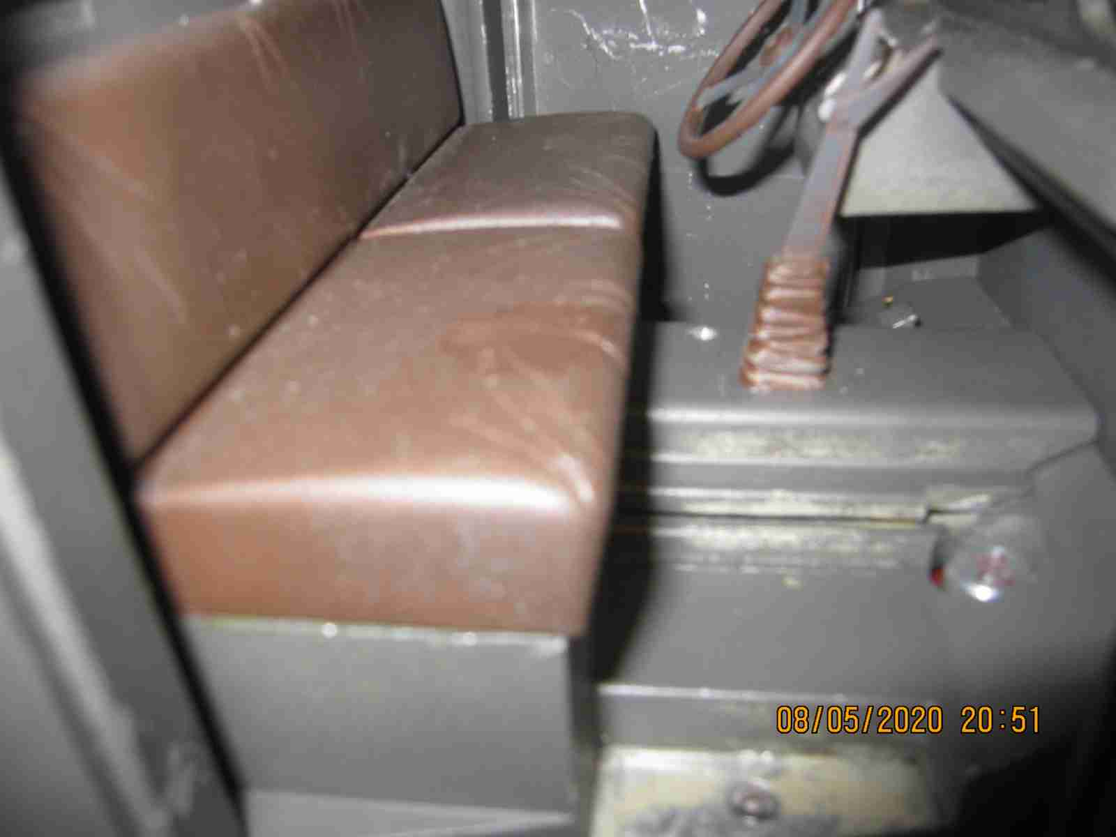
The shift mechanism is concealed under the seats and center console....
I'm keeping a steady pressure on installing the radio systems. As I write this I've done the preliminary installation for the most complex part: the shift mechanism for all four trucks. I have receivers bound with some servos and main ESC installed on three of the trucks already; presently working on Kaelble 2 with Kaelble 4 just before this one able to be driven reasonably well. Truck 2 is drivable but I've taken the time to fill in the absolutely disgusting number of holes previous owner/ owners) have made in this thing. I was going to post before and after photos but I really stopped myself questioning the utility of that. I used methods I've developed and maybe seen here on this site elsewhere. There was just a really large number of useless holes in this mode's cab now happily all filled in very securely with aluminum, pins where appropriate, aluminum 'rivets' and aided with JB Weld used in a 'bondo' role. It was work I'd rather no have had to do but I believe the end result is worth it. I think I'm simply going to make a matrix of the 4 trucks and which controls are complete and update it as the work proceeds. I am using a Turnigy 9x transmitter using a later version of ER9X OS. So far it's worked very well. Jerry 08/31/2020
|
||||||||||
|---|---|---|---|---|---|---|---|---|---|---|
| Truck | Main ESC | Steering | Shift X-axis | Shift Y-axis | Overdrive | Locker 1* | Locker 2* | Winch Control | Lights/ Sound | Run test |
| Kaelble 1 | Yes | Yes | Yes | Yes | Yes | Yes | Yes | No | No | Yes |
| Kaelble 2 | Yes | Yes | Yes | Yes | Yes | Yes | Yes | Yes | Yes | Yes |
| Kaelble 3 | Yes | Yes | Yes | Yes | Yes | Yes | No | No | Yes | |
| Kaelble 4 | Yes | Yes | Yes | Yes | N/A | Yes | Yes | Yes | Yes | Yes |
I made an aluminum shift gate overlay for the right stick on the transmitter I'm using. I also removed the spring for this gimbal and made a drag brake to keep the y axis movement fixed so the shift control will stay where I want it. So far this is working pretty good. I'd wanted to use eepy on my PC to manipulate the settings and re-flash the system that way but since I migrated my main desktop to win 10 I seem to have lost the USB driver that allowed me to connect. Somewhat annoying. Using the menus directly on the transmitter is a little tedious but it works. At least since I'm making the installations as standard as I'm able the 'copy model' function of the OS really helps. Jerry 08/31/2020


The speed controls, ESC, I've used all have built in battery elimination circuits- BECs. I've found that with all of the servos on these models demanding a great amount of power they overcame the BEC's ability to keep up. The symptoms were clear: extremely erratic performance of the servo controlled function in particular the steering servo which on truck number two I am using a powerful Savox example. Every time I attempt to steer the truck all hell broke loose and it reminded me of old AM radios of yesteryear or Robbie the Robot wildly waving its arms! Fortunately eliminating the output of the BEC is simply pulling the positive lead from the plug and insulating it with a section of heat shrink tubing... I will publish a test of a truck soon..
Locally we seem to be coming out of an awful period of rampant wildfires up and down the coast with attendant miserable air quality. The Plague (COVID19), heat (as high as 108f 42c), extremely bad smokey air all made for some miserable days: cooped up in the house with windows closed with heat did not make for good model building days! Still I've made progress; I'm about to begin on the redio installation for final Kaelble, my Number 3. In some ways this model may prove to be the most interesting for it has components of my making- engine/motor, transmission and rear axles. While working on truck 1 I noticed that it is faster than the previous two I worked on. I realized this is due to the fact that I made the motor- engine myself and I don't recall that I used as low of a gearing ratio to what the OEM units have. This in turn was due to not paying attention to the published ratio of the factory units. This shouldn't effect the overall performance too much but might do as a future project- to rebuild the motor to have a lower ratio; additionally this simulated engine is using twin electric motors of much greater efficiency, power. This last truck I'll commence work on uses electric motors very close to OEM specs and I believe an internal ratio also closer to the OEM units. Jerry 09/16/2020
Truck number 3 is going to be a lot of work I see. I realized that I'd done the bare minimum of servo installation on this truck with no provision for steering, gear range (overdrive) selector, and locker servos. Further in doing brief engine and transmission tests both failed; actually I'd not pinned the output shaft of the motor to its coupler and was relying on a set screw which came loose under a load. That has been fixed. The transmission will be more work I believe; firstly the overdrive selector only half works- the low range will engage however the high range will not. Unfortunately of all the transmission's functionality: this is the least accessible and will require at least a partial disassembly of the gearbox to determine what the nature of the failure is. There is a short compact drive dog which is engaged by the small lever on the rear left side and I suspect this mechanism has somehow gone wrong. My plan is to work out as much of the radio installation as possible then circle back to this problem afterwards. Other than that the motor seems at the proper ratio and speed and the gearbox seems quieter the more I run it. Even if I had no issues I'd likely would drain the oil inspect the mechanism and close it up with fresh oil. I suspect the latest oil I've decided to use has seemed to have stopped leaks being somewhat more viscous, aided in quieting down the transmission and is aiding in seating in all the gears including those I made myself.
I believe I've corrected the problems I've encountered so far. I've pinned the gears in the internals to the engine which I had previously relied upon set screws which had let go during tests. In the transmission I replaced the one gear that had both proved noisy under performing- this was one of 4 I'd cut myself due to the need for the double sided hub one of which needed to be machined to form the drive dog. the teeth were not formed correctly at all; I did a poor job on this gear unlike the other 3 which have performed well. My solution to build up a gear on a commercial (Madler) gear by both brazing and riveting the extra metal then machine it as needed. This was difficult but yielded a functional part- just how long it will last remains to be seen. I have included some photos of this part. I believe as time allows I will revisit making a new gear by cutting a better version. Gear cutting I found is tedious not very pleasant work really and for the one gear I replaced I was simply sloppy- I shouldn't have used it at all in retrospect. I fear I'm growing weary of this project; as soon as the radio system and truck 3 overall is proven out I will take a break from this project. I have questioned my taking on 4 of these extremely complex models as once. I have been working on them for the better part of 2 years! I believe I've already written to this but the radio implementations are among the most complex I've done in some time and would not have been easily done without the very flexible radio systems available today. Knowing that these models first were introduced in the mid 1990s using radios of that time would have made installing the control system a real nightmare.
![]()
![]()
![]()
![]()
Test video of truck 3. Jerry 09/26/2020
The basic radio installation fot Truck 3 is complete as may be seen by the table above. I plan to do more extensive run tests for this truck as I've mentioned as the components are of my own construction. I think some rearranging and fitting will be required for the cab as I may have been a little free with my positioning of the one side mounted shift servo although I'm hoping nothing major. Once the cab is fitted and I can do the run tests I'm going to clean up my work areas and take a break from these trucks however there is still the winch control ( a secondary ESC) and lighting. Lighting will entail the dash instruments, headlights, taillights and a number of other lights. I'm hoping to use a TBS Mini control for this plus sounds and I've never used one so there will be a learning curve. Some of the tail lamps I need to come up with a solution for all 4 trucks and three trailers as two lamp bodies are common and I don't have enough to go around. I plan to replicate these in pewter which is a little sturdier than the original lead. I'm looking forward to moving on but I also wish to finish these trucks completely. Jerry 10/1/2010
The YT video clip above is a test run in my backyard along the cement work that rings my backyard. Apologies for the poor videography; always fearful I'll drop my camera. The truck worked perfectly despite my attempts to run it off the path. I'd made some other improvements to my transmission while I had it apart to resolve the one overdrive gear issue I had. I improved the selector's alignment detent and overall alignment of the selectors themselves including the groove the selector bar (button?) that slides between the gear clusters. It seems to operate with much more surety. Even though I broke the steering servo horn at the last moment by going over a depression in the cement it was an easy repair and served to highlight that these trucks are definitely for smooth surfaces only! I'm going to spend some time to see how I can best utilize the TBS Mini (TBS clone) to provide some decent sound and control over the lights on the model. It's basically going to be whatever I can accomplish with the capabilities of the 9s transmitter and the TBS Mini board; I'd prefer not to add a multiple selector extension of some sort. I basically have head/taillights, rear deck spotlights and instrument panel which I would like to control independantly. I've already been able to attach the board to one of my desktop's USB port and flash it. Now to understand how the outputs are to be assigned. After this I may install the winch controls on the trucks and perhaps wire up the lights and speaker for sound. However nnoe of these are pressing. I'm considering the project's major efforts complete 10/03/2020 Jerry
It's been over 2 months since I last wrote here on this project. I've not sat idly on these trucks. I've been working on making the tail light assemblies from pewter. I made a mold of high temerature -capable silicon rubber and have made quite a few copies. Next I've prepared some 16 assemblies and made red and amber lenses (yes I know amber hadn't been used during the time these trucks were made - 1930s but I acted on a whimsy!). I've also obtained tiny leds to illunimate these lamps. I need to assemble and wire them for the trucks and trailers. Part of my time has been spent preparing for another project: an Armortek 1/6 scale M3 Lee but more on this in it's own page. My immediate goal is to complete trucks 2 and 4, wired, sound, lamp and painted. I want these two complete- I can work on the cab interior later. I'll follow up with truck 1 and 3 which needs the most work. Photos to follow.... once I find where I put them!. Jerry 12/06/2020
Working away on the trucks, two of them anyway. Number 4 and number 2. They've been painted a green-grey save the rims on truck 2. Also I've wired the head and tail lights and using the TBS mini to control these. I must admit whereas I once had grand ideas in making all manner of lighting feature I now think I'll limit it to the head and tail lights. These models are complex enough and just to wire these lights on one truck took days as I worked out how to run and (mostly) secure the wires. I have a problem with the sound on the first truck I've done, I get a proper start sound, then brief idle then it roars to full throttle no matter what I do asnd I don't recall it doing this when I first worked out the settings. Frustrating. Not sure it's the cause but I am running the ESC without the BEC active (+ lead pulled from connector plug) but I'll run tests. I've reached the point where I've become nearly burnt out on these models and want them done. Truck 1 and 3 need the most work but happily I was able to purchase from Hr Stehr and he quickly was able to send me the engine compartment side panels and another set of fenders so now these two will be complete; nothing more is needed. Jerry 01/04/2021


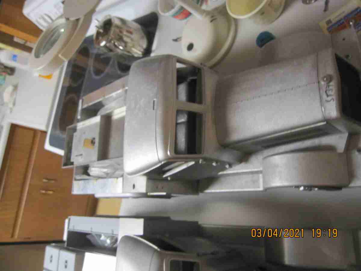
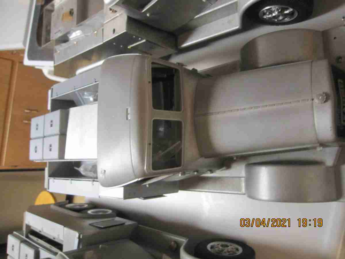
I make progress. All 4 trucks now have mostly complete bodies, including number 4, the panels of which I'd used to make bodies for 1 and 3. I have finished most of the more difficult tasks for these trucks including all remaining winch tasks (pins, wiring) only threading in the steel cable remains on the last two but they are ready for it. I began priming truck 1 but I need to fill some of the screw locations. I will prepare these two for painting likely isn a month or so and then they'll receive final low level detail, windows and interior lighting as I get to them. I don't like the steering servo and machanism and want to change it; it is weak, prone to failure and mechanically unsound but that will be down the road. I also unhappy with the issues I've had with what seems like interference but I believe is in fact power issues: there's simply too much demand for power to run all the servos, sound and lights simultaneously. The steering servo having to turn those large heavy solid rubber tires under the great weigh of the truck has proven daunting. In any even this project is complete enough to move on. Jerry 03/04/2021
All for as they are today 3/4/2021

Truck 4
Truck 3

Truck 2
Truck 1