King Tiger, regular production turret
I started my King Tiger project before I moved to my present home in 1990. I had ordered the set of track castings before I moved and they ended up going to my previous address. I was fearful that I'd lose them. This project more than any other spurred me on to learning the basics of foundry work. Other than the tracks I made everything else myself and so have no one to point to as to how it looks.
Some particulars regarding the model. As it was begun before I was able to cast anything the upper and lower hulls were fabricated from .250" thick 7075 aluminum plate. The maingun barrel is thickwall steel tube, which had a .250" ( or so ) id. It's essentially a gun barrel without grooves. It is very heavy unfortunately. I would have been quite happy to use thick wall aluminium tube but it is so difficult to find here. The turret, entire engine deck, mantlet, parts of the wheels, sprockets and idlers were all cast as were various small items. The model is very heavy without anything in it but preciely how heavy I don't know. Compared to one of the Maier Panthers it feels substantially heavier. A Maier Panther weighs in around 70-75 pounds so I'm guessing the Tiger should weigh 85-90 pounds with gearbox, engine and all it needs. The torsion bars, all 18 are .125" piano wire, captured at the inboard side with a setscrew, running through the hull side in a 1" long brass bushing and fixed to the swingarm with amother set screw.
As it is so heavy I don't expect it to be a stellar performer but then that isn't ever my plan anyway. My plan is to use a Saito FA TS90 twin 4 cycle engine. The engine has a useful speed range of 2,000 to 10,000 rpm. I plan to air cool the engine with a aluminum sirroco fan. Further to improve throttle response I am planning to use an aluminum flywheel as well. This to provide power to a Maier speed gearbox.
Some of these aspects of the model can be seen in the following series of photos

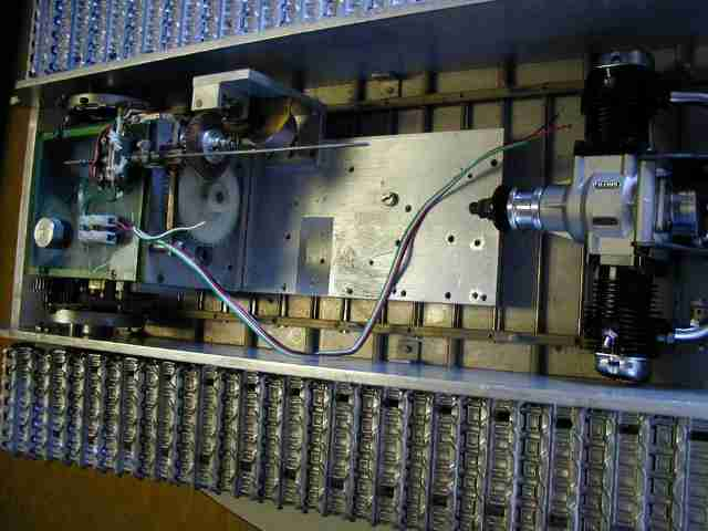
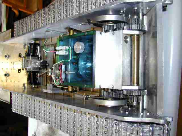
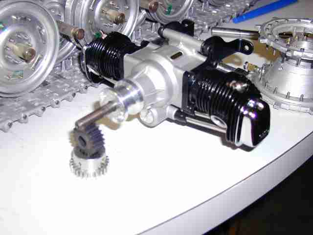
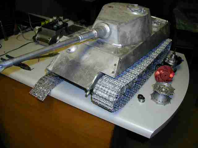
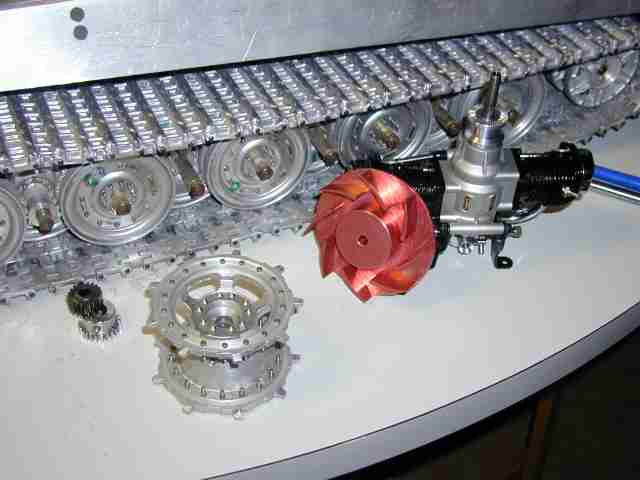
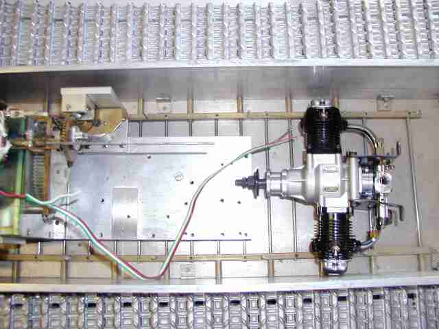
I have started by working on the output shafts mounting the sprockets. I ordered and received new 20 tooth steel mod 1 gears to engage the transmission outputs. The .375" steel output shafts ride in twin ball bearings. Once I have the sprockets and gears mounted to the shafts I will fit and align the gearbox. After that I will beginworking out the design and building the "powerpack" essentially the engine as a standalone self contained unit including a self starter, flywheel, fan/shroud and mount. Also as part of this intial model - "revising" and making things previously just trial fit as firm/fixed aspects of the model I need to revise the mechanisms I used for fastening the lower hull plates together. Also the roadwheel 'hubs' and shafts need to be shortened and new parts made. I'm seeing the shortcommgs of my wheel renditions but I'll probably go forward with them. I still have hopes of building a Jagd Tiger and would probably make or acquire a better wheel as part of that project. The Jagd Tiger is just a pipe dream at this jucture as this model is far from finished and I no longer even have a clue as to a source of reasonable priced 1:10 scale King Tiger tracks....
I'll be working on this slowly; a little bit each evening. It gives me a chance to think things through yet make measurable progress. I'll be puuting up quite a number of photos to document this. I'll probably find aspects of this model that won't work as is and be forced to rebuild tham; I'm hoping those things will be small in number. I'll also be taking a break from time to time to revisit the rear deck of my Sturm Tiger which still needs to be finished, I just didn't wish to hold everything else up while waiting to find/make the needed parts... Jerry 02/10/2007
Back again for a a brief update. I finished the initial work for mounting the gearbox to the lower hull as well as some modifications to the output shafts to secure the sprockets and gears to enagage the gearbox.
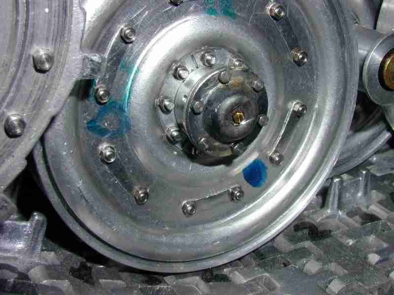
I realized to finish up the drive train, to ensure everything is aligned I would have to work on the road wheels. Working on the roadwheels meant making the parts that I hadn't yet finished. At this point I have to say these wheels aren't quite what they could be for I made them at a time before I had better information as to their proper details. I did make them to be held in place with nine bolts as the major pattern on the full size tank but the full size wheel has an extra pattern of six bolts I could not duplicate. I used 1-72 bolts but it would have been better had I used 0-80 bolts so all 15 bolts would have fit. Anyway... As part of this work I needed to simulate the 3 clips that were used to retain the roadwheel on the axles. I made a series of tools to cut the rings and make the holes for the bolts. I need to decide how best to simulate or actually cut the rings I made into the three clips. What follows is a series of photos of the wheels and their parts. I have to say that even considering the amount of work that I know went into making these wheels I am not opposed to making or buying better wheels down the road. Jerry 03/06/2007
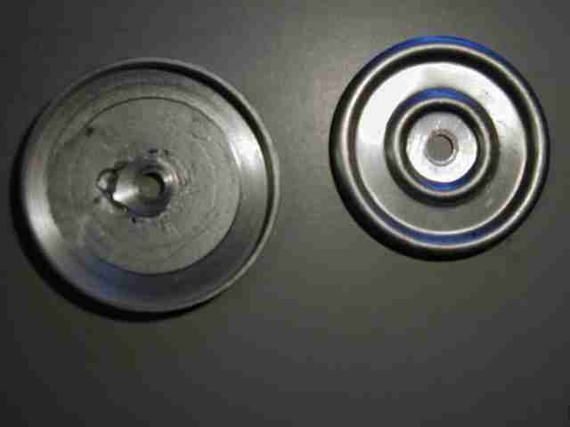
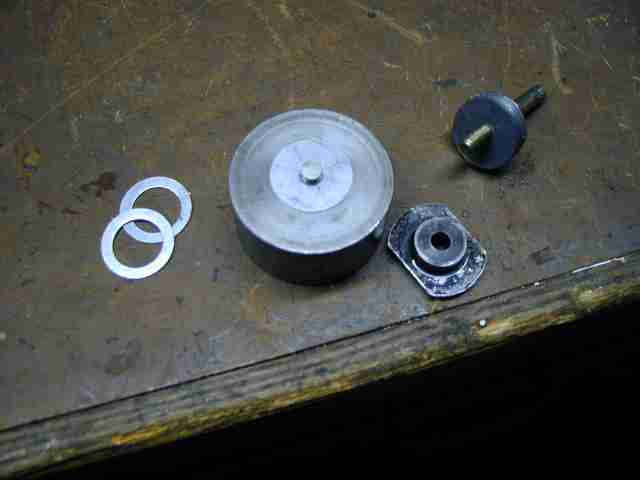
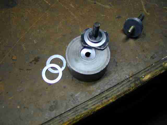
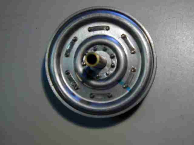
Here's one of the wheels with the ring attached and also the simulated center shaft.
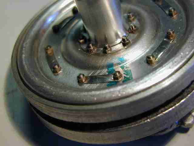
I knew when I got back into this project I'd be spending much time doing things just to get the model to a point where I can make some progress. One of those items is addressing the wheels. While I did a lot of work to fabricate them to the point you see in the topmost photo on this page there remains so much to do. The late German tank wheel or variations of it shared by Henschel King Tigers, late Tiger Is and a few Panther G vehicles is, in my opinion deceptively complex to model to any degree of accuracy. My wheels aren't that accurate but should hold their own among larger King Tiger models when I'm finished. It would be relatively easy to mold a cover piece in resin more accurately depicting the wheels' face and glue it in place. My wheels are fabricated in aluminum, steel and brass and the screws you see are functional. I'm in the middle of assuring the alignment of the wheels with respect to the tracks and sprockets although this is pretty much done. In the last week I've made all the center axle "spindles" ( my word ) to simulate the mounting area for the steel roadwheels. I had to make two fixtures to turn the parts on my lathe. There is a short (10) and long (8) piece for a total of 18. I fit them prior to finishing the rings and nut/bolt sets for each wheel. I wanted to know how close the fit would be with all the difficult parts mounted. It is tight as can be seen; there will probably be some scraping in rough terrain ( but I don't believe full size King Tigers really when on wild cross country runs did they?) but I think generally it will be ok. I am making an assumption in that because the wheels basically roll on a undulation carpet of the track it is very unlikely that one roadwheel will have a widly diproportionate vertical movement to its neighbors. I need to reset the torsion bars on the front end a wee higher initially to compensate for the weight of the gearbox. Right now the tank has a bit of a rakish look to it! I hadn't ground the mount point for the bars yet for this very reason; when I made the tank I hadn't known what gearbox she'd be carrying...
I asked the question on the UK tank forum how ( in radians, degress or what have you) far a full size King Tiger road wheel was expected to travel and I was told 20 inches for a Tiger I! That translates to 2 inches in 1/10 scale. Now as a matter of fact my King Tiger has about 2 inches of ground clearance up front; more in back ( remember the rake at the moment- to be corrected ). Now, no one said if that was an absolute; I envision the movement of a roadwheel to be described by a point moving along a arc or the absolute distance a fixed point would move in a straight line. Here's Where the 20 inch deflection quote makes no sense to me: where was the measurement of 20 inches taken? did the wheel center decribe an arc 20 inches in radial distance or did it move straight up 20 inches ( I doubt it). It seem coincidental that the hull bottom clearance and the deflection are about the same! In fact the references I've just went and read (http://www.lonesentry.com/tm_tigertank/) specify that for Tiger I ground clearance is 1 foot 5 inches or 17 inches and for the Tiger II it is 1 foot 7 19" inches in front and 1 foot 8 inches 20" in back ( There IS a rake! WooHoo!) Does that mean the Tiger I would bottom out? ( I doubt it!!) I just wonder if the aspect of the Tiger I was misread or misspoken?? Hmmm. 20 inches or 2 inches in my case seems an awfully violent movement for something as large and heavy as either the Tiger I or II. It would seem to be very hard on the torsion bars...I know the wheels do deflect quite a bit but Hmmmm. I'm going with a much more modest deflection target...
So things that need to be done to the suspension are:
I continue to work on this model a little bit each day.. Jerry 03/22/2007.
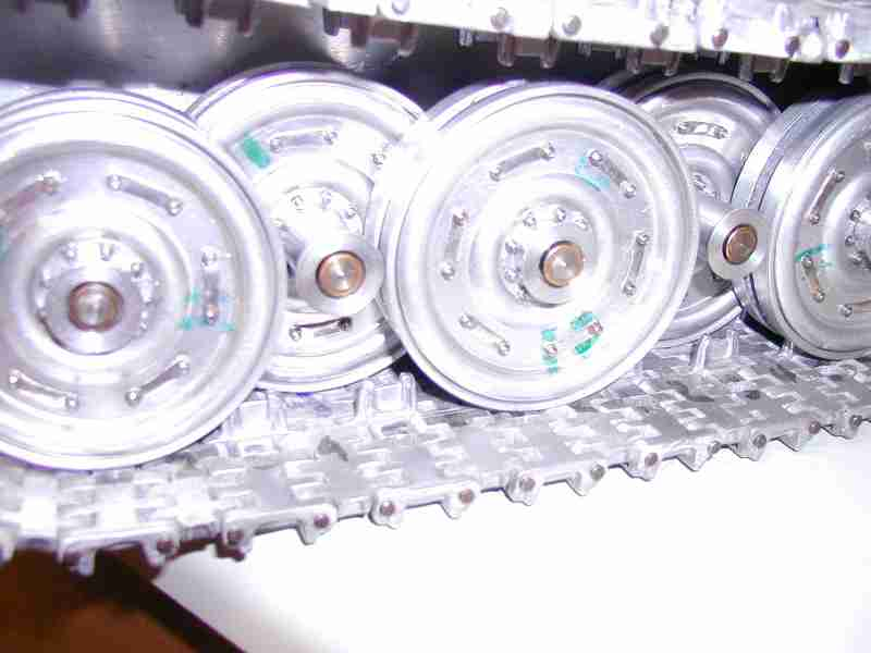
they don't really look half bad here...
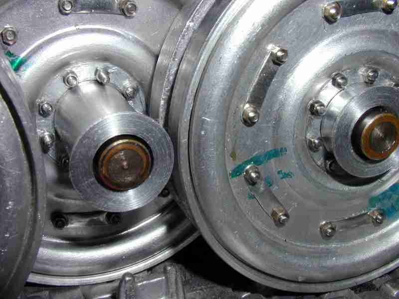
Back again(04/21/2007) for a brief update. Since the last time I have finished making the rings and reassembling all of the wheels. The initial phase of this was ironic. With everything done on the wheels except the hubcaps I assembled the model and looked at it for a day or so. I found I couldn't abide how the wheels interacted with the sprockets and each other. I consulted the drawings I have and read that that the wheels on the full size King Tiger are 195mm across both wheels and the gap between them to accomodate the track guidehorn. That translates into 19.5mm for my model. I measured my wheels at anywhere from 21 to 24mm. A few mm may not seem a great amount but when you realize that the wheels overlap each other and the sprockets ( recall I've had issues there ) it makes for an uncomfortably close fit. Recall the scraping I identified earlier. Well to make a long story short I decided to completely diassassemble all 32 wheels, 700+ screws to unscrew and reset. This was very boring. But anyway I reduced the thickness of the back portion of my wheels, the cast 'cup' or pan I'd made by turning them on the lathe. Upon reassmbly ALL my wheel assemblys are between 19.5 and 20.1mm across; this translates into greater uniformity across all the parts. I can see and hear the improvement. Time,while painfully boring was well spent.
As part of remaking the wheels as detailed above I alo made a fixture for setting the 'set' points on the torsion bars; this is where a set screw engages the bar at the anchor point on the hull floor and at the swingarm. This is neccessary to keep the clearance set to the proper height.
05/28/2007 I've been plodding along on the suspension until I've reached the point where I now need to address the outer wheel axle cover or as I call them "hub caps". I haven't a handle on what they're really named especially in German.
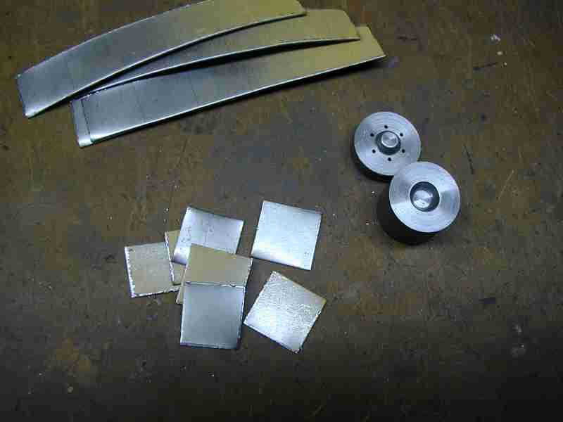
I made a working sketch of the piece based on drawings, photos references and other materials I have. I made an approximation from aluminum on the lathe. Midly unsatisfactory and the prospect of turning 17 more ( plus spares ) indentically by hand wasn't too appealing. I decided to make a die to press them. I tried a varity of metals the same thickness I designed the die for, brass, aluminum and steel. Steel, which I'd annealed for before pressing seemed to give me the best result. In addition to the die, I made a number of drilling and shaping fixtures to hold the caps while finishing them. Below is a series of photos I took of the process.
The raw material, .050" sheet steel. Also pictured is the die I made to press them.
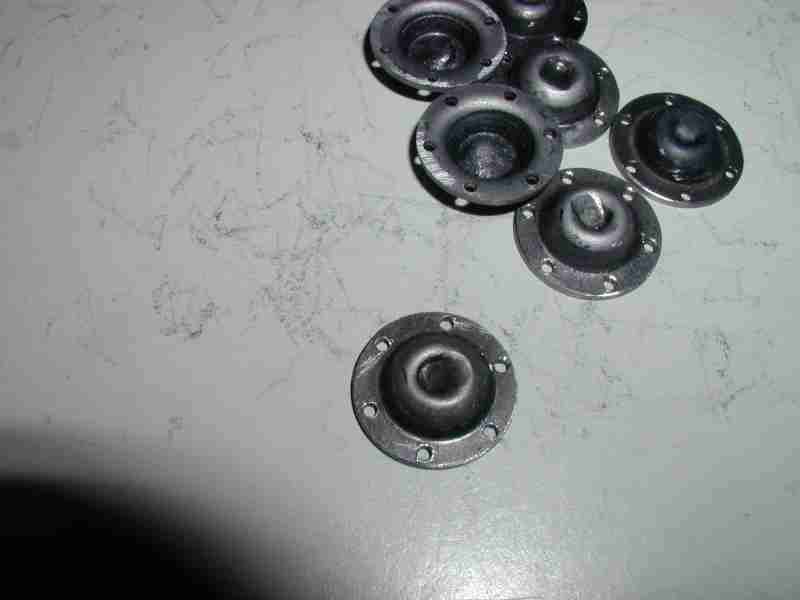
Pressed cap, drilled, in the foregound turned caps and the holding fixture used to turn them
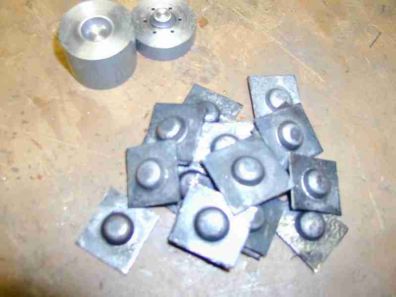
Here the caps have been 'dimpled' to simulate that slanted depression characteristic of King Tiger wheel covers/hubcaps.The caps
A fitted cap, with central small hex nut, a brass 00-90 and the cap itself held in place by 6 0-80 stell hex screws.
I used a series of fixtures, actually fixtures and adaptors to drill the 6 bolt pattern on the caps as well as the hubs themselves to ensure as much as possible uniform alignment. So far all seems well.
06/02/2007 - After some days I have finally completed preparing all 18 wheels for the hubcaps. I have to say drilling and tapping 108 holes for 0-80 threads was nerve wracking. I managed to break a tap on the first wheel I did but also managed to remove the borken part AND salvage the threads as well so no real harm done. After that I rather "got in the groove" and didn't break another. I actually used the broken tap ( which had been broken before ) as it made an excellent bottoming tap. A photo will follow.
I also decided to jump ahead with modifying the upper hull front cross member as it hit the upper part of the mounted gearbox where the shift contol and terminal block is. The affected area of the upper hull was akward to get to and machine on my small mill. Modifying the cross piece was a necessary yet unforseen operation as I could not have known what gearbox I would ultimately use when I laid out the hull. The Maier gearbox I am using isn't that tall but rather the cross member of the upper hull was uneccessarily thick; in fact as I recall Maier's Panther upper hull didnot have a cross member in this area that went all tyhe way across as his Panther hull ( cast aluminium) and my KT hull are of similar configuration.
--o0o--
07/16/2007 Where have I been? I've been working on the engine mount and cooling assembly. Right off I'll say I've been having second thoughts! It is a neat idea but executing it is a chore at best. The design for the mount and cooling shroud isn't coming to me easily! Just below is a photo of where it is as of today:
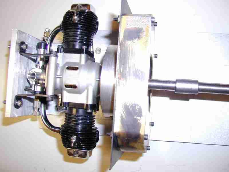
This doesn't seem like a great deal of work but trust me it is! I've not had a lot of time to do this. We've been in a crunch at working rewriting one of our older systems in Java and honestly I'm dead by the time I get home :-( ! On top of that all else usually leaves an hour if I push it from 10:30 to 11:30 or so late at night, yaaaaawwwwwnnnn.
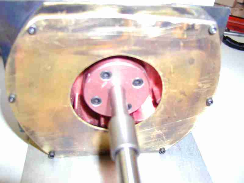
Moreover since yesterday I've been rethinking my reasons for wanting to use this complex and complex to cool engine in the King Tiger. I wanted enough power to be sure and the wonderful sound of the twin 4 cycle. I thought it would be a good thing to do albeit a stretch. Well here's my latest take on this. The original Webra 6,5ccm / .40cid "Blackhead" RC is a wonderful engine. Strong, simple and durable. I've got enough spare engines and parts to keep all my tanks running for years to come. The engine is rated at about .88ps or if you wish .85hp at about 14,000rpm. The Saito on the other hand is rated at about 1.4 hp at around 12,000rpm. The Webra has a steel cylinder liner; the Saito a hard chrome plated aluminum cylinder wall. I've made the cooling fan / flywheel assembly for the Saito large to push a lot of air to the twin cylinders. It isn't very tolerant of high temps. And I haven't even worked out a ducting or shroud layout from the fan housing to get the air to the cylinders. The Webra uses an extended crank pin to drive a rear mounted axial centrifugal fan to for air across the solo cylinder head.
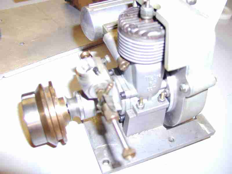
The Saito/ flywheel/ cooling fan/shroud/ starter and clutch assembly is going to take up a huge amount of space in the tank. There's only two specific positions I can place the engine due to the height of the cooling shroud. I'll need at minimum a 12oz fuel tank, preferably a 16 as after all this is a .90 not a .40 and since it will run rich as an aid to cooling and lessened stress on the engine the fuel will go quickly. I doubt it will be a pleasant layout in the tank. The Webra is much smaller and would be a proven layout.

Lastly and this has bugged me since yesterday: with a peak engine output of 700hp the the original "full size" King Tiger had a power to weight ratio of about 10hp / metric ton; the Panther at 45 metric tons was a bit better at 15hp / metric ton. My model will be weigh close enough to 100 pounds so for sake of argument I'll call it 100 pounds or about 1/22 (0.0454) of a metric ton. For the King Tiger 10 hp per metric ton * (0.0454) = about 0.45hp /100 pounds. That says to me a reasonably authentic power would be about .50hp for my King Tiger. The Webra is rated at .85hp and the Saito 1.4. Let's look at that last figure. Going the other way; 1.4 hp per 100lb * (22) = 30.8hp /metric ton or for a 68 ton tank 2094 hp! In the their dreams!! Unless I'm mistaken I don't believe any modern tank has that level of power. So needless to say for all the reasons I indicated I am leaning, at least in the interest of time thinking seriously of reverting back to the original webra 40. As the engine that came with the gearbox is only partially configured for the gearbox this decision itself represents a goodly amount of work as I'll have to make a new flywheel, starter and clutch components. That the tank won't be a speed demon is acceptable. I may consider working through the cooling shroud design for the Saito but I'm afraid my decision is rapidly being made for me...more to come. -Jerry
08/21/2007 I'll start with posting progress photos and I'll add text later!
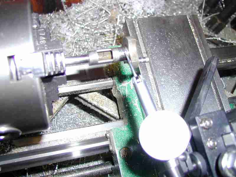
In the photo below I am chaeck the crankshaft the the engine to make certain it will run true. After measuring this original one I decided to replace it with another. Requires taking the crank pin from one and pressing it into another. Not so much work and assures I've improved the accuaracy of the driveline.
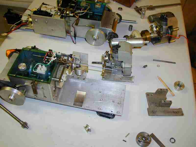
The gearbox/engine before work begins. You may notice all the nasty holes that were in the base plate of the gearbox are still there. I later filled all of them.
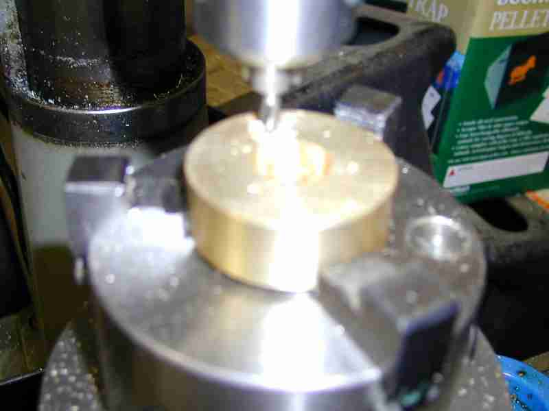
Making the flywheel
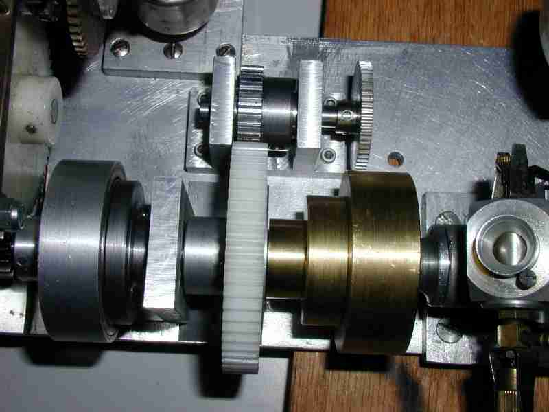
Part of the starter,. At this point I've already made the flyweheel, drive shaft, starter gear/roller clutch housing, support bearing block and clutch backing plate. Notice all unneccessary holes are filled; gives so better a presence do you think?
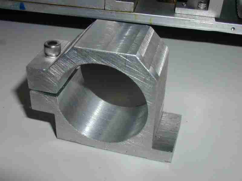
Making the starter motor mount

Motor mount nearly finished
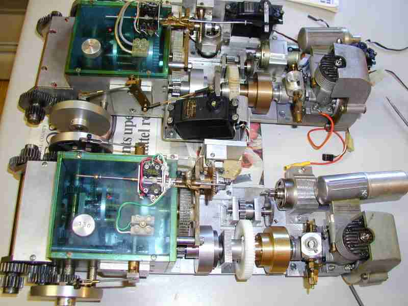
Two assemblies side by side, one completely Maier original, the other with my own parts
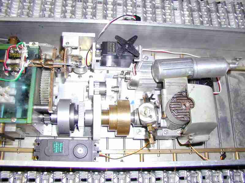
Servo placement "reasonableness" check.. At this point the gearbox is fully mounted on the tank floor plate.
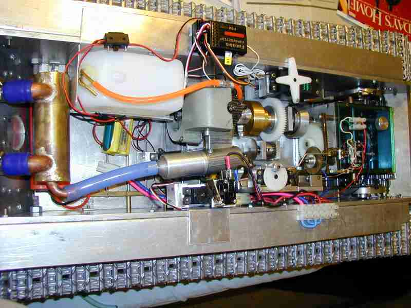
Hello, Jerry here, it is Thursday the 20th of September,2007! Nothing happens quickly with this model! I've made progress but with other obligations it is slow going. The model is just about ready for a trial run. From the photo immediately below you may see that just about all internals are where they need to be. Some elements will be mounted to more permanent locations one the layout is proven. Some aspects of the wiring harness need to be improved for safety, mostly prevention of wiring coming in contact with hot exhaust components. The fuel cell placement is correct but very close to final exhaust manifold. The fuel cell is protected from direct contact to the manifold but I'm not happy about the tight fit. If I must I will change to a smaller cell size. I wanted to have maximum fuel capacity. Calls into question how I would have carried sufficient fuel for the 120 Saito. I'm hoping for a test run prior to this weekend. I will post photos of that....
The following 3 photos show some details about the exhaust pipes
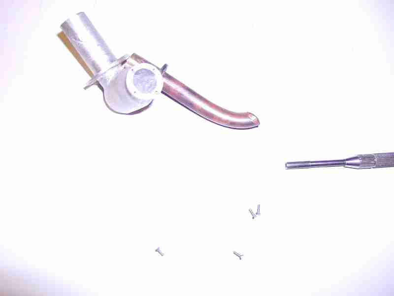
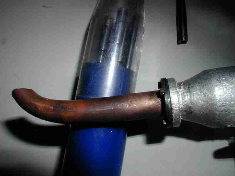
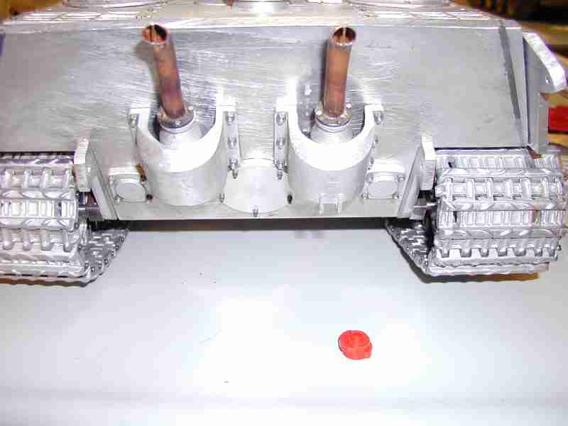
I will probably finish up the lower hull completely then take a break from this project to work on some other things and clean up my shop(!). I won't stay away for long though as I wish to finish this project completely and soon. I still need to finish my Sturm Tiger but I'm waiting for news about rear deck parts saving me the time and work of making a pattern. And I wish to develop an idea I've had to use components I have to make a dual differential geabox that I could use in my Hetzer project. Jerry
Aha!
09/22/2007 Well I tried it! I decided to take a break, no that's not quite right, delay doing my chores (that I stayed home to do... ) and try the King Tiger. After some fiddling with the carburettor she fired up! At first I was simply going to run up the engine and that's it. But she was running so well I decided to see how she'd do in gear. Oh my, all that work has paid off! She ran beautifully!! Better than I'd hoped. First I ran her sans upper hull then the second run with upper hull. Stopped, started, turned left, right wonderfully. I really have to learn how /when to steer with that long 88 though! I had a couple of close calls and one rose bush is a bit smaller now. This big tank has the ability to climb he step to my deck!! I was impressed. I ran the model in 1st, 3rd and reverse gears. I used up about 350ml of fuel. Wowzers! No major problems arose, some minor electrical noise due probably to an improper antenna; the receiver antenna needs to be properly set up. Wiring harness for the raio system needs to be properly mounted. The most annoying thing to crop up is a leak in the exhaust system. Oily exhaust all over the side of the engine and the surrounding servos ( not good ) and tank floor plate. Many table napkins are busily at work as I write this soaking up the goo. I will fix the leak: there's only two possble places where it could come from. I don't quite know where it leaks but I suspect the large extension to the webra muffler- a factory item. Happily not a drop of oil escaped from my exhaust system's rearmost components I just made: dry as a bone they remained. So I am pleased in the extreme! It was a joy to see running. A success! WooHoo!
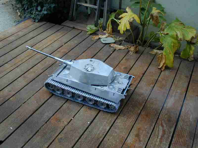
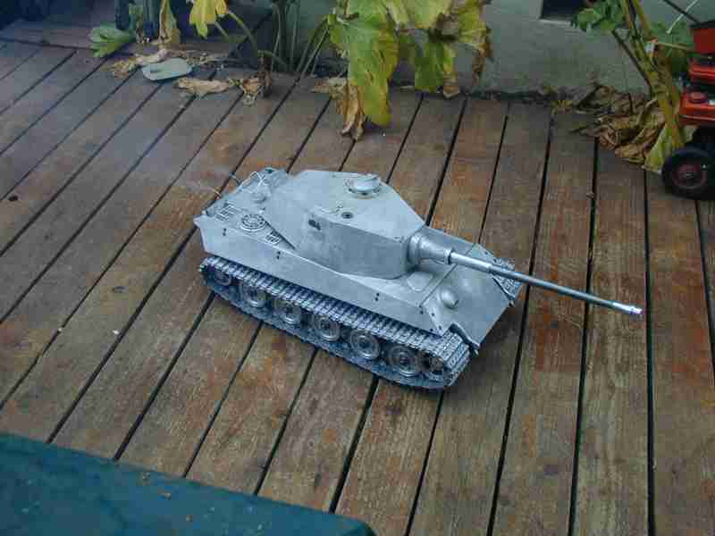
What's next? I'm going to actually take a break from this model; 90% of the work being done. I need to determine the best way to make the turret rotation and main gun elevation components. I need to finish the rear lower plate as there are several component - covers which need to be made.. long story short there's a lot of upper hull detail that needs doing. Some of this will be facilitated by using the parts from Wecohe I bought: Bosch headlight, tool brackets, tools, etc. So I'll finish it shortly but a break first is welcome... Jerry
-- 12/14/2007 -- Hello all Jerry here. I've resumed the construction work on the King Tiger. I am flat out intending to copy Jochen Maiers turret ring layout as implemented in his later Panthers. This design works very well. I received the module 1 internal gear to be used as part of the turret ring. This was a costly gear at $105.00 so when I machine it I want to do it correctly! The two major operations that will be done to this piece is to first turn a flange then grooves on both side having a semi circular profile which will form part of a large bearing. The development of these components is detailed below:
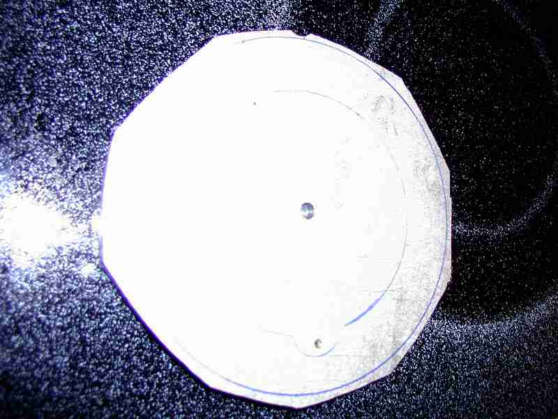
This is the chunk of aluminum I began with. Years ago I had purchased abot 800+ pounds of aluminum scrap from IBM ( there was a conversion of equipment and the local CEs could sell it for coffee fund money!) which I intended to be used for my foundry work but there have been sections like this that are usable as is. I laid out the part with the cutout for the drive pinion where an existing hole was. If I was going to make many of these I would make a pattern and cast them it would save so much time. By this time I have roughed out the part by cutting excess material away.
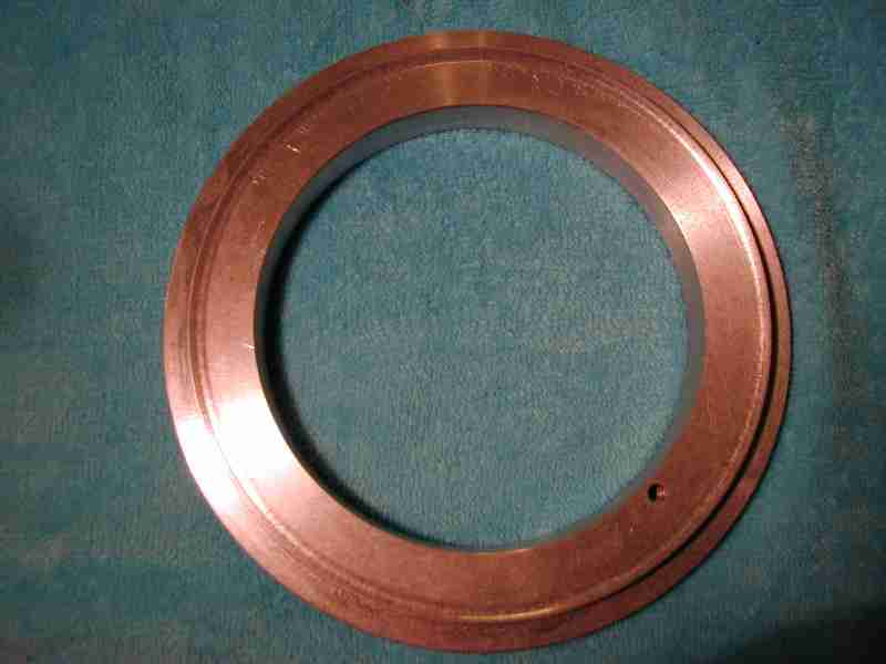
Here the part was turned to finished dininsions except for the pinion cutout.
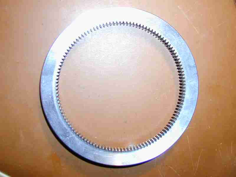
Here is the internal gear prior to turn the flange and bearing ball grooves
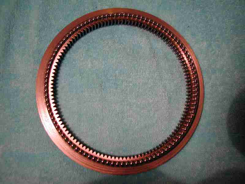
Here is the internal gear with its full complement of bearings, 102 of them.
Here is the module 1 internal gear after turning the flange and bearing ball grooves (top and bottom)
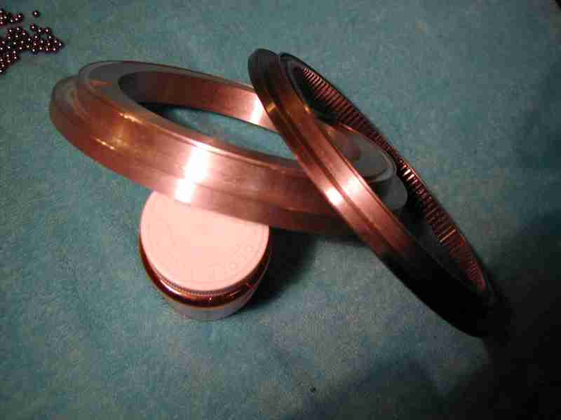
Here are two of the three main sections that go into the turret ring. The large flaged part is the bottom piece which will be attached to the upper hull, the internal gear which will be attached to the turret base. Not shown is the top plate which will secure the assembly together.
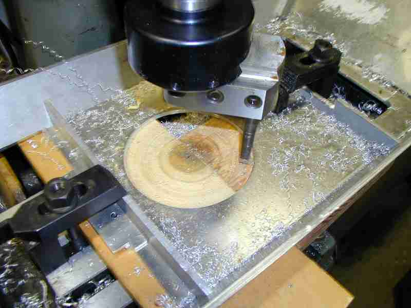
Here's a photo of preparing the upper hull for the lower part of the turret ring.
Hmmmm Lucky error or....???
After reviewing my handiwerk for cutting the turret ring parts and the required gaping holes in the turret floorplate and upper hull I discovered to my annoyance( to put it VERY mildly) that the front of the turret when swung around will impact the engine room hinge if turing clockwise or the forward engine air cleaner cover if swung around from the counter clockwise direction. Firstly, many epithets were leveled at my measurements and calculations, then I lamented that when I first made this I didn't have proper information and finally what can I do to fix this piece of petaQ!!! ( to envoke my rudimentary Klingon ). I searched my materials remembering that I had purchased Dr. H. Maus'(seriously that's his name) fabulous study of the King Tiger many elements of which are dimensioned. He has the displacement or offset of the turret ring with resepect to significant elements of the upper hull deck plate. Comparing what I had done based on my initial calculations it turned out that I had set my turret ring about 1.07" too far back on the upper deck and turret floorplate. !!! Arrrgh! At this point I should say how this came to be. When I first made the turret and turret floor castings I didn't have the above mentioned drawings but they turned out reasonably well nonetheless. I wanted to attached the turret to the upper hull in a temporary manner but have it located properly with respect to the over all tank. So I found the proper location of the turret, centered a small hole for a 4-40(!) screw and loosely attached the turret; it had been this way for at least 1-13 years until now. Being aware of the location of the turret I went ahead and used this hole as the starting point to bore the turret ring shown above. When all was done the turret was properly located and runs great on the turret ring. Except for the one little problem indicated previously! Well this just won't do I said to myself, I have to fix it. I considered the best way to do this. In short while the turret is located correctly the turret ring is not; if located properly forward much less of the turret front actually moves in a circle that is to say the turret ring is not on the middle of the turret's center line. This was the problem; I needed to figure out a way of either making new parts, casting another floorplate wouldn't be a big issue although not altogether appealing and filling in the upper deck and recutting the turret ring's hole, the requisite 1.07" forward.

Lower ring fitted to upper hull; should be 1.07" further forward. You can see how close is the fit to the engine cooling shroud.
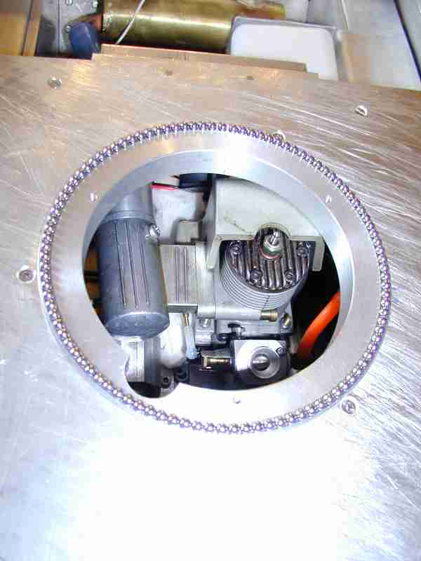
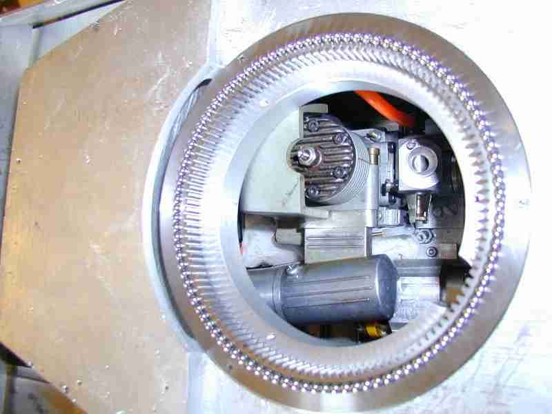
Lower ring with its full complement of bearing balls
Ring in place on top of lower ring (bearings) with its full complement of bearing balls
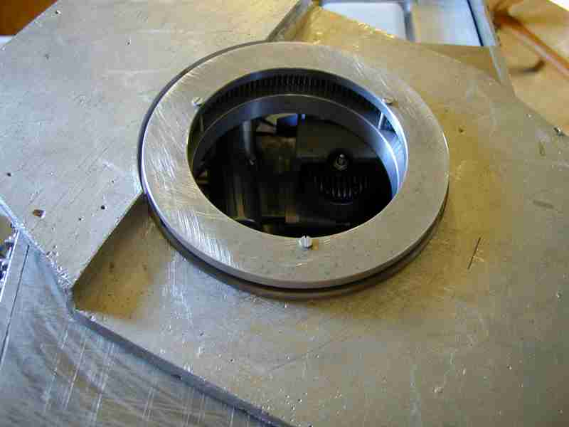
Complete turret ring, temporary fasteners.
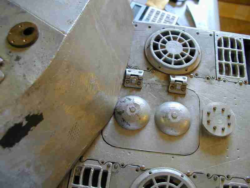
Limit of clockwise rotation.
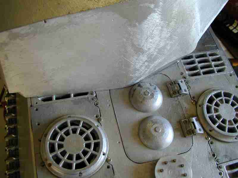
Limit of counter-clockwise rotation.
So where's the lucky part???
As I pondered this I knew well that I could fix it, not a question. Next I said before rushing into this let's see what havoc you'll wreak if you do this. So I carefully marked out where everything should go and the turret front will handily miss all those rear deck components it tried to knock off earlier. Assesing where the lower part of the turret ring will be I stopped in my tracks! The flange of the lower ring would rest solidly on the cooling shroud of the engine and glow plug! Even If I remake the shroud from brass so as to be thinner I can't move the glowplug! And as it is the upper hull is impacting (temporarily) the exhaust system and when I allow for clearance there the upper hull will settle a further .080-.090". It will never work if I move it forward or at best it could possibly cause some major re-engineering which I don't want to do. There are too many if's and maybes for me to do the work which is substantial and then the clearance are too tight to be sure. It works the way it is for certain and at this point I want certain. I decided instantly I'm going to leave the turret ring where it is! I was wromg to put it where it is, I should have double checked my calculations. I will buy off on not being able to swing the turret around a full 360 degrees but instead perhaps 270-280 degrees! So it while it is wrong from an accuracy standpoint it is lucky from a functional standpoint that I accidentally put the turrent ring too far rearward! I've found I rarely swing a turret around a full 180 while running anyway so while I remain mildly annoyed ( I may in the future fix it anyway ) I am ok with moving forward leaving this aspect as is... That being said it still bugs me because while few except for armor enthusiasts will notice it I know it is wrong...Jerry 12/23/2007
01/03/2008 ..... Happy New Year everyone!.........Well anyone who knows me also knows the issue with the turret location is too difficult a pill for me to swallow so in keeping with the Blog-like nature of this construction article I'll tell you what I've done: I'm well on my way to correcting it. I bought some new T6/6061 .190" (3/16" - 4.8mm) plate to make a new upper hull deck plate for the model. I won't cover the details except that the way I made the upper hull years ago I was able to unfasten and slide out the old plate so I could make a new one. In making a new deck plate I actually solve two problems; that of the turret ring placement and an older problem of the deck plate basically just being too short by about .3". I've got most of the work done as of writing this but I also need to refit the rear engine deck and modify the turret floor plate. I've decided to repair the turret floor plate instead of casting a new one as being it is raining and damp I'd just not prefer to do a sizable pour. I hope to have all of the corrective work complete by the end of the week.
01/12/2008 I'm happy to say I have completed the modifications to the model required to properly position the turret's pivot point. I've checked the rotation and it is now able to turn a full 360 as it should. At this time I'm working on the rear engine deck, a component I didn't finish when I first assembled the model; probably noticable are the less than scale semi round head stainless steel screws I used to keep it together over the years. Refitting and new parts will be made to finish it. Next I've also got to fit the turret drive; I have a gearhead motor selected for the task. I believe my last major task will be to decide how to make the elevation mechanism for that enormously heavy maingun. I've toyed with the idea of remaking the maingun but only if I could find suitable aluminum tubing. As far as I know the maingun tube is ok from a appearance( needs surface smoothing) but it is just so heavy. After that comes all the detail work on the upper body and turret, some remains on the lower rearplate as well. That should all be fun. looking ahead I must decide how to best apply the anti magnetic mine paste aka Zimmerit. I will probably experiment on small pieces of aluminum. I also need to pull the transmission and engine for two things: I may install a Webra telemetry system to monitor engine temp and rpm, but not a certainty. Secondly I need to solve the exhaust leak and retighten everything that may have loosened.
02/09/2008 While progress has been slow I've not been standing still either. Early in January I was lucky to be able to meet with Per Sonnervik and his lovely wife Birgitta when they came to San Francisco; Per and I paid a visit to Jacques Littlefield to see the latest on the Panther. We also spent time here discussing modeling and other topics before during and after dinner on two occasions. I am greatful for a long and wonderful friendship with Per and Birgitta.
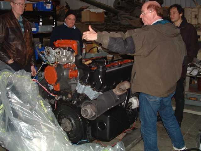
Jacques explaining the recent work on the Maybach to Per and I( Per is to the left of the engine, I'm in the dark blue watchcap behind the engine) at our recent visit
After resolving the issue with the turret ring placement I proceeded to begin work on adding details to the rear engine deck as well as strngthening the infrastructure for the entire component. I remade the central vent/armor cover on the rear as it was much too tall. I made the fuel and coolant filler caps, antenna access plate and recess for the antenna base(Antennenfuss). I have an aspiration to attempt to make the base in rubber like the original but... I made the spent shell hatch for the turret and cut the opening on the turret housing. I made a fixture to uniformly bend the lifting loops for the turret and mounted thos as well.
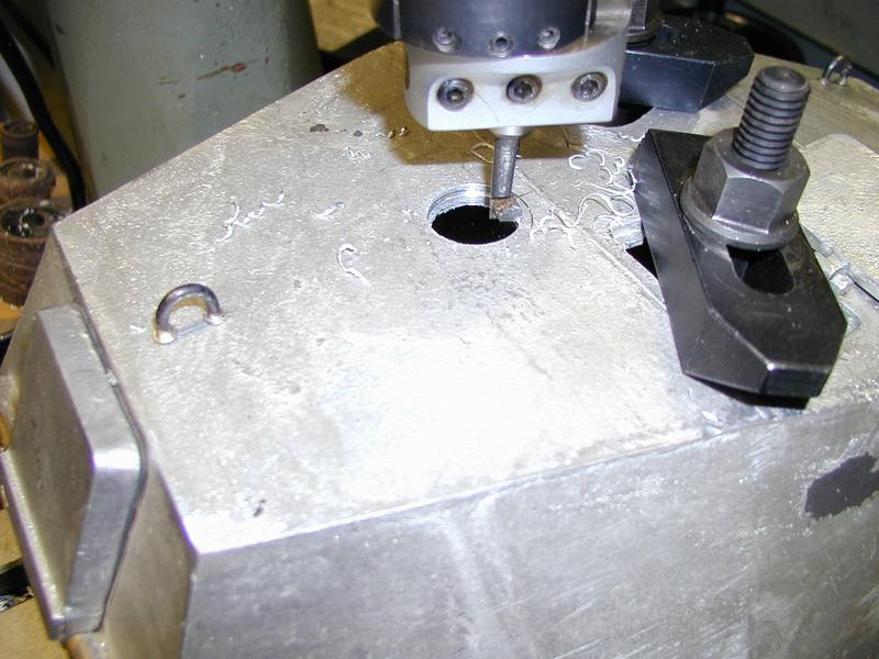
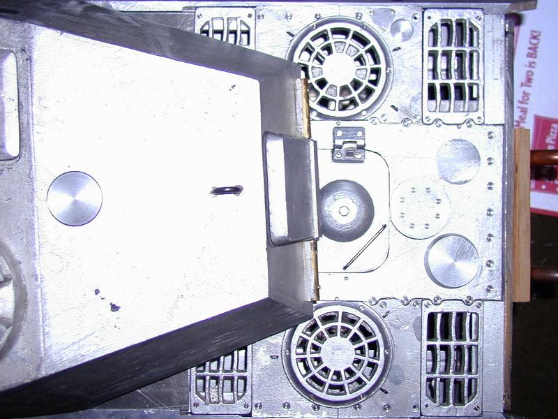
05/12/2008 I've not been sitting still on this project although progress has been painfully slow. Having to make every little bit while expected takes time. And I've been making considerable progress on my JagdPanther also. Since my last entry I have taken care of some long standing needs on the model. 1) making the maingun articulated (pivot) so I am able to implement an elevation mechanism, working this one out ate a lot of time. I will post photos of my solution shortly but in summary it is the first set of main trunnions for a model of mine that ride in bronze bearings! 2) finally, and I dreaded it, machined the reliefs for the driver and radio operator's periscopes. Mounting the upper hull taxed the limit of my milling machine. But it is done for the most part. 3) made re-enforcing bracket for the lower rear plate so it is no longer just loose. Made of .125" steel. 4) made remaining cover plates for rear plate of lower hull
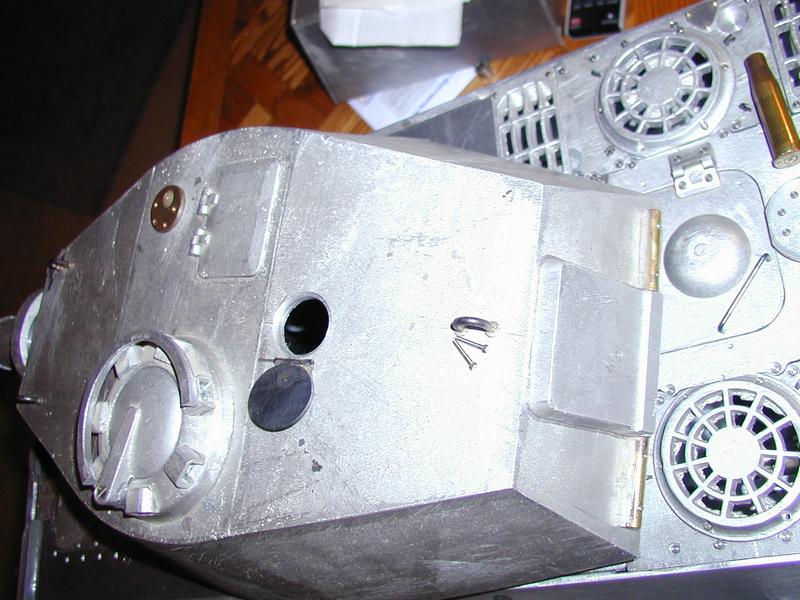
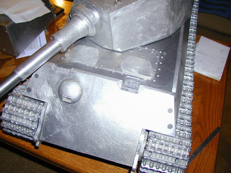
Well it has been nearly a year since my last entry for this project as today is 04/12/2009. I've not been entirely sitting on this project. I've been gathering information and several components for the detail level work. Thank goodness for Uli and his company Wecohe. I've just ordered another set of his detail parts for the King Tiger. I also just made the brackets for the 20 ton jack mounted on the rear plate.
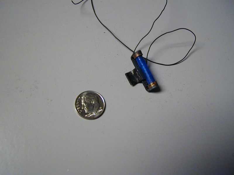
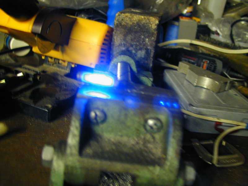
I had purchased several of Wecohe's Kolonnen Licht sets some while ago. I assembled the photo etched parts but I have to say at .012" inch thickness I fear they are too fragile. I know Wecohe was shooting for scale thickness and appearance but I know how fragile parts fare on a rc model. The kit came with a light unit consisting of three surface mount blue ( type 603?) LEDs on a sliver of pc board with two leads for power. This assembly is already located inside a section of rigid ~5mm plastic tube. The other component is a fret of photo etched parts. I muddled through this, it is very difficult for my clumsy hands plus I didn't have any instructions!After assembling the photo etched frame I just thought it too fragile. I also decided I wanted a translucent blue tube instead of the clear original. I've never seen a real one close up so I don't know what they look like. Long story short I ended up buying .250" blue plastic rod from Tap plastics, boring a small section to the id of the Wecohe supplied tube and also turning the outside to 5mm. I fabricated a lamp frame from steel and brass. Stronger probably but not as "scale " in appearance? I'm not sure I'll use this first effort as it may be a bit larger than scale. I'm going to try making others; so I may use this one on my Sturm Tiger. I think I'll buy some leds of my own so I might experiment. See photos below:
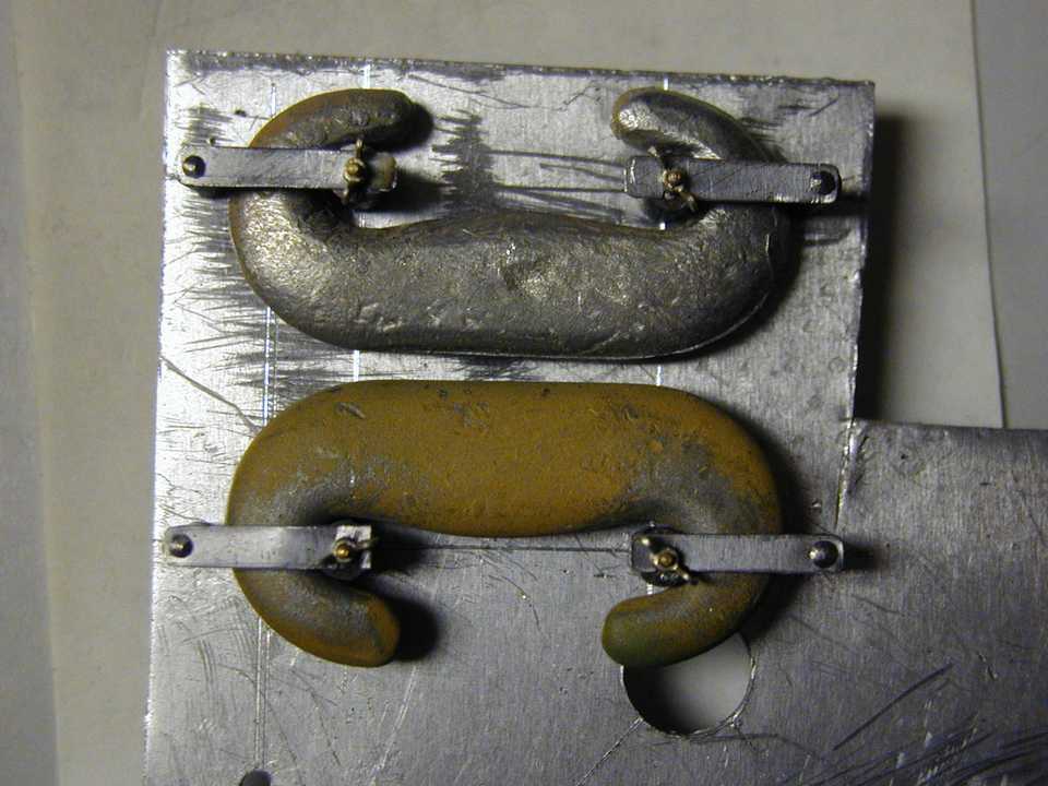
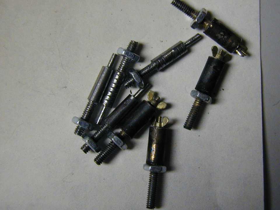
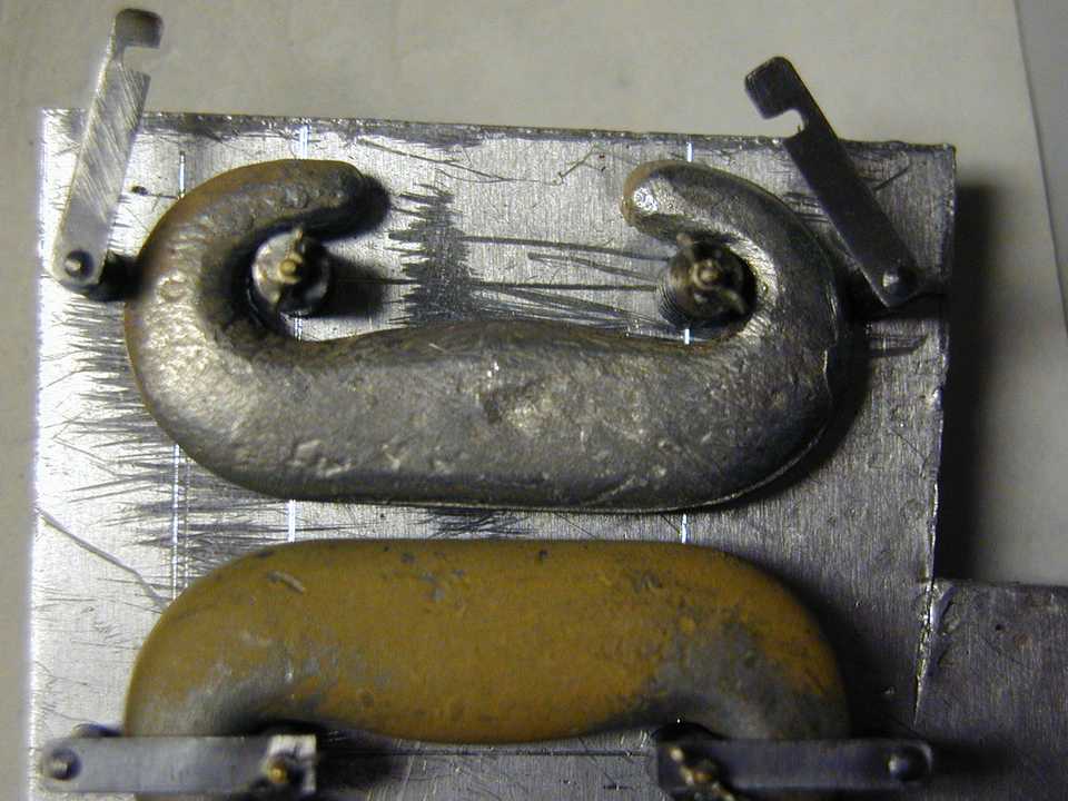
04/29/2009 I keep toodling along at a leisurely pace making the detail parts for these models. Below is a series of photos of the components I've made for the double c-hook brackets found on the rear of the King Tiger and some SturmTigers I've seen. I've made two sets, one for each model. Thank goodness for those marvelous wing nuts that Wecohe sells. They are functional and happily so are my c-hook brackets. The small piece of aluminum scrap I have one set of parts mounted on is both test fixture and will also serve as template to drill the models' rear plates. There remains a small amount of cean up on these parts but they are essentially finished.Jerry
06/21/2009 As may be seen from the photo below I have begun to mount the small details on the rear plate. In fact I made a new rear plate as well as the original had a hideous gap ( about .1" ) on both sides; it had been a very earlt mistake when fist cutting the plate. Si far I've mounted both mud guards and the C-hook clamps. For the most part things look pretty good, not perfect but pretty good. There are some final fitting of the plate and I noticed some adjustment of some torsion bars is in order but on whole it is coming along well.
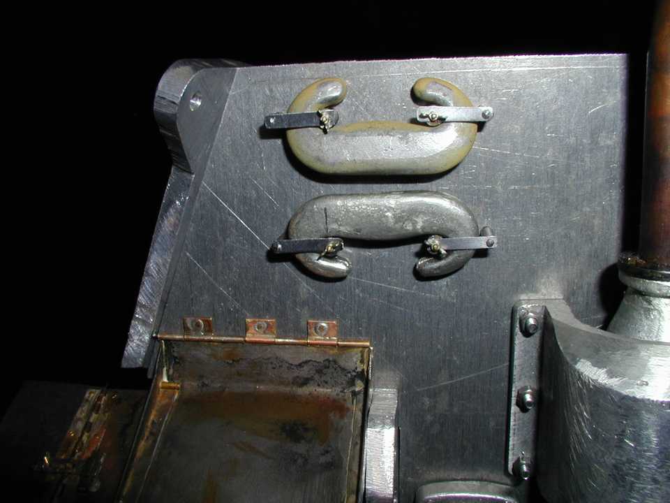
06/30/2009 Today I celebrated another milestone, it was my birthday. Which one? Nope, tmi my friends tmi. Well I've been working on getting the components mounted on the rear plate and below you can see most of them. I have yet to mount the 20 ton jack; I want to revisit the mountings. I have found that making test mountings on scrap makes for better placement on the model. I can make as many mistakes as I need (!) on scrap bits but no harm will come of it. In the end I am able to use my final test piece as a drilling fixture for the model. It has working pretty well for some of the more complex mounting systems on the rear of the King Tiger. As I have said several times already I will take a breather from this model; doing this latest work has been rigorous. See you in a while! Jerry
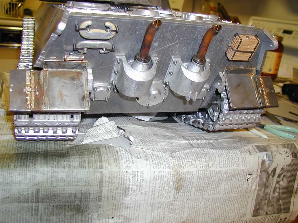
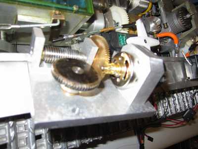
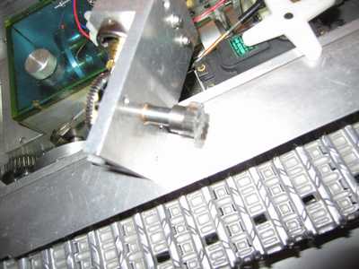
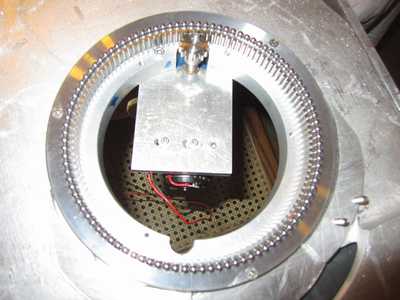
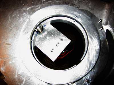
10/11/2010 It has been over a year since I've posted anything of my King Tiger; I've not done a lot but rather small items except until just recently. I've been trying to address fundamental needs across all of my models. In particular the main gun elevation mechanism which is lacking on all Maier Panthers, my JagdPanthers and of course the King Tiger. There are also everal others in my collection needing this piece of fundamental gear. In the case of My King Tiger it has also needed a turret rotation drive and that is what I recently created.
as with many other things I've done I decided to clone as nearly as possible the very usable and powerful design Maier made for his Panthers. Oddly enough the interior space in the King Tiger arpund the turret ring has become quite scarce. The options for placing the drive asre very limited and the configuration that that location will allow really dictated the Maier format drive. I made up a drive using components I had and the turret spun so viomentmy it was dangerous! Nes I substituted a very small "eacap" brand gerahead motor which was quite powerful but took about 5 minutes to rotate the turret 360 degrees. This forced me to re-examine the worm gear and initial reduction gearing I had chosen. The worm itself was a multi start ( spiral ) type instead of a single start so it wasn't giving me the reduction I wanted. I went back to my gear supply and found that I had single and multi start types intermixed but they were of the exact same physical dimensions.Replacing the worm also required changing the worm wheel and again luckily both components were the same size as the others. The initial reduction needed to provide 6:1 reduction to feed the worm pair but I only had slightly less than 4:1. I located suitable gears in my gear collection although they are a coarser pitch than I would have liked. I made the neccessary changes to fit these new parts and the turret speed was down to a managable 14-15 seconds for a full rotataion. I brought the topic og King Tiger turret speed up on the RCU forum (http://www.rcuniverse.com/forum/m_10056957/tm.htm) and it created a spirited discussion. I am using a a esc to control the turret drive so I can limit the speed as required. See photos below:
=====================================================================================================================