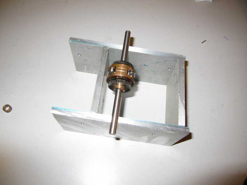
Transmission for a Hetzer.. my first self made transmission.
I've been wanting to start this for years. It pushes my machines to their accuracy limits and it isn't always relaxing work but still I have to try it. I don't know how well or if it will work first time but here it is: my first attempt to build my own gearbox, capable of being powered by a glow engine..... This opportunity is provided by the requirements of building the Hetzer. Jerry
First the basic housing was made up

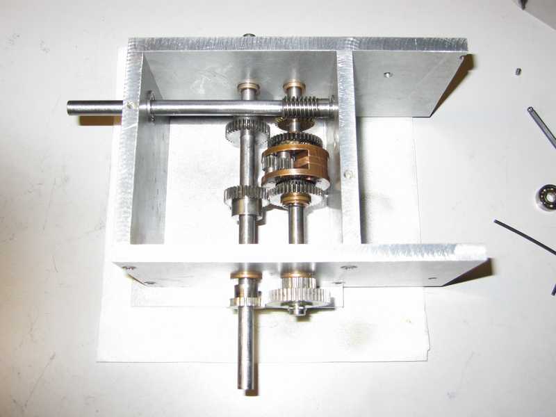
The differential was installed then the worm drive. It was a chore to get the center to center distance for worm and driven gear correct as I really didn't have the proper specs for this pair.
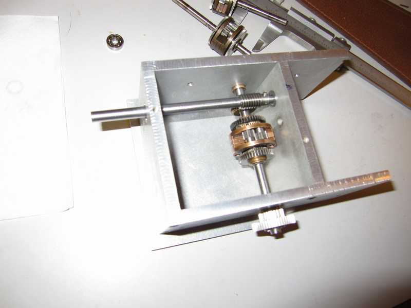
The first fitting for the spit shaft to split power to each side. I cheated and used thin paaper beteen gear to ensure correct spacing while I prepared the bearing points.
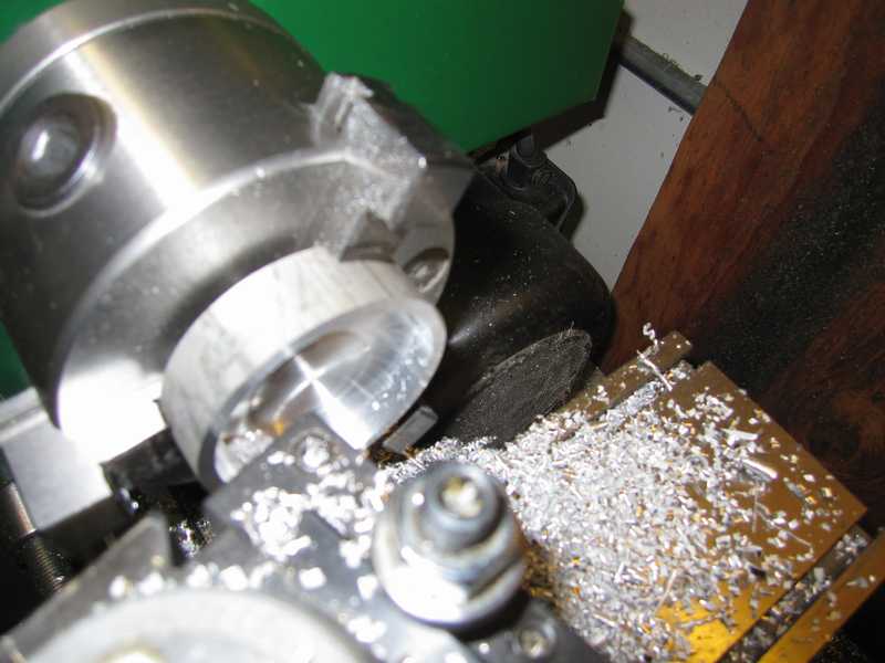
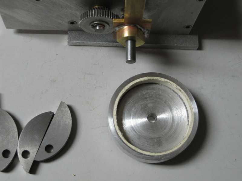
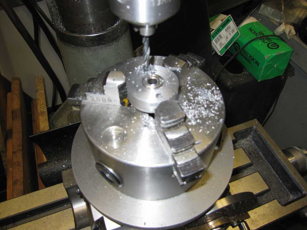
Cutting a brake drum
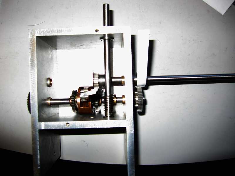
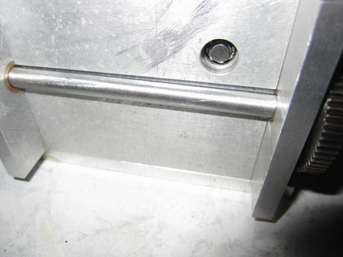
Both half shafts fitted with gears and bearing points. The inner bearings are mounted on a pollar shaped to fit just aft of the differential housing.
Trial fit of brake drums

I'll post progress here as time permits. Jerry 12/2/2009
I decided to make the brake drums from aluminum and glued a layer of a think gasket material inside to see if that will make a suitable lining. It will be an experiment. It was only recently I realized that Maier used Schluter helicopter clutches and bell housings for his some of his Panthers and didn't make these. Not sure about the brake drums as they looked the same as the clutch bell housings. At some point Maier reversed his methods: he initially kept the brake drums lining- free and put lining on the shoes but later switched to a lined drum and plain shoes. I used his last version. I made the shoes from cast iron bar and the bells from aluminum. Initially he made both from cast iron. Below is a photo of one of the drums with lining:
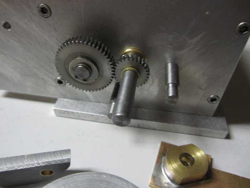
I first made a test fixture, what is not shown is a disk I cut at the same diameter as the inside of the lined brake drum so I could set up the brake mounts in the correct position. The frirst photo just shos the brake lever and the two brake shoe mounting posts.
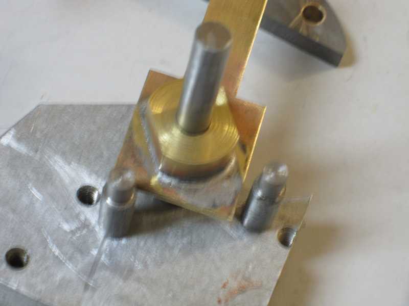
This second shows the shoes mounted
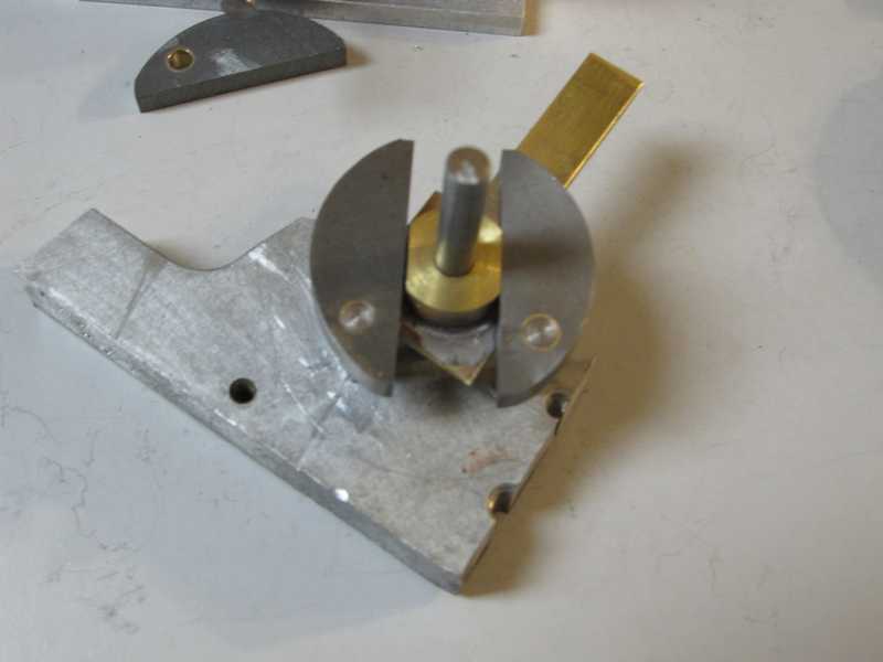
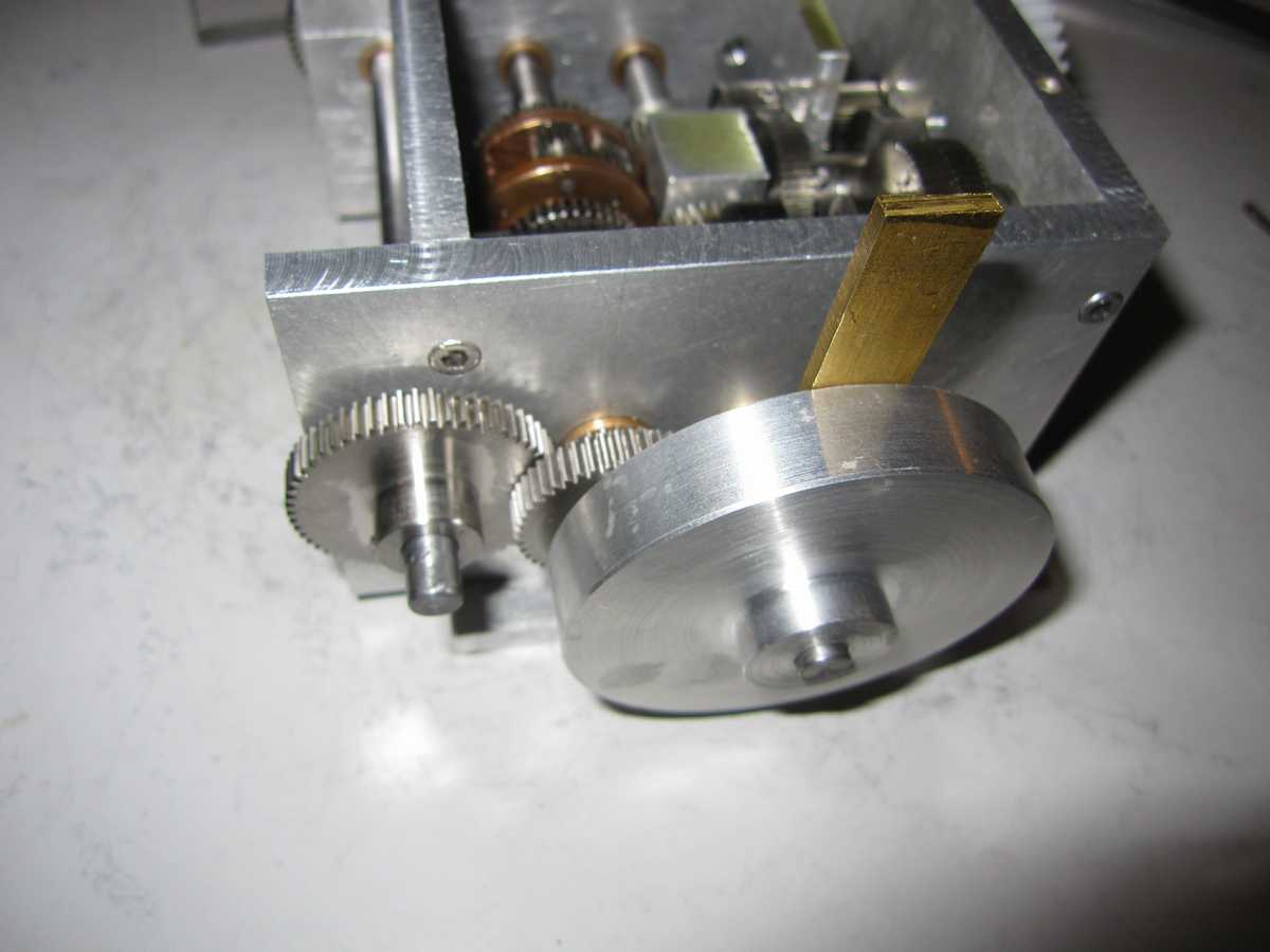
This third photo shows the brakes mounts installed on the gearbox housing, you can see the output shaft (split shaft driven from the differential ) with its small pinion gear and brass spacer:
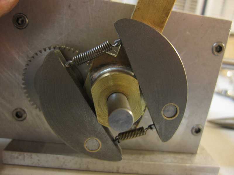
Shoes installed ( with return springs):
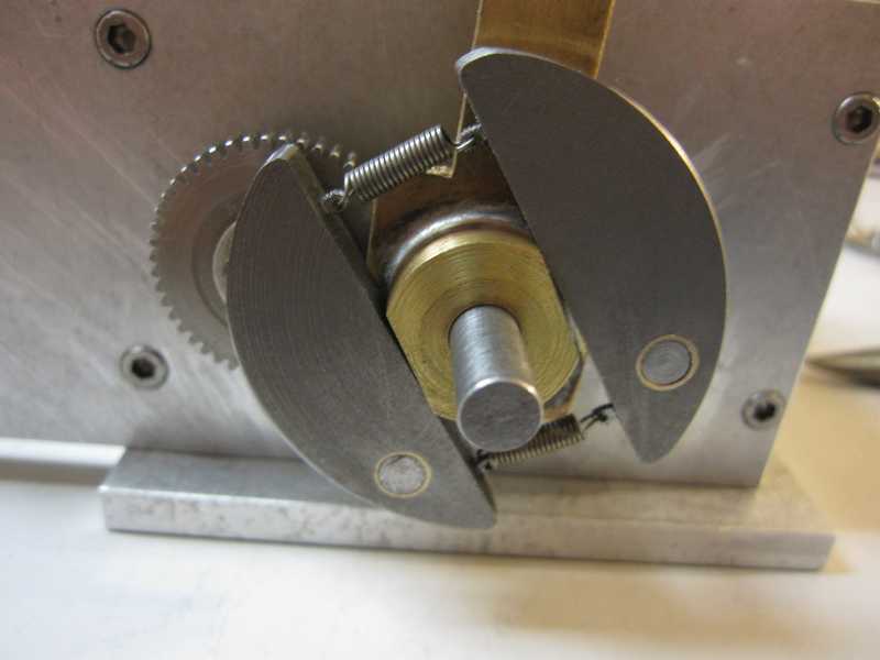
This next photo shows the braked in their deployed( engaged ) position, as they would be to stop this side if the gearbox for a left turn:
With brake drum installed, you can just see the return spring inside the drum in the ipper photo:
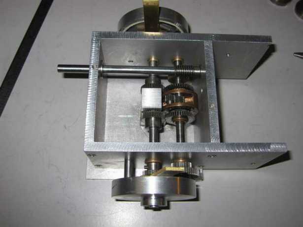
I have to decide on what final reduction ratio to the final output gear that will be just to the left of the gear on the differential shaft, shown in this sane photo from above. The gear is the one retained by the circlip. It is a free running gear driven by the split shaft to it's right; it will drive another gear which I have but wish to ocrease the reduction of so I will need a larger gear. It will have the actual final drive gear pinned to it which will actually engage the gear of the drive sprocket shaft.

I will also now begin to work out how I want the shift mechanism to work in order to select forward and reverse. The long input shft you see above sticking out to the left will be cut flush with the gearbox rear plate. The forward and reverse gears will be mounted on it. Engaged through an idler for either forward or reverse as required that will be the last stage of the gearbox. A lever system to perate the brakes is to be created as well. At this point none of the gears are actually pinned to their respective shafts so only limited testing can be done. Jerry 12/15/2009
01/10/2010 Here is some progress. I just tonight trial mounted the intermediate gearing. I position this gearset slightly lower than the main drive sahft so I could take advantage of the central bearing post. It made a handy point to anchor this shaft without having to make a new one especially in the cramped area.
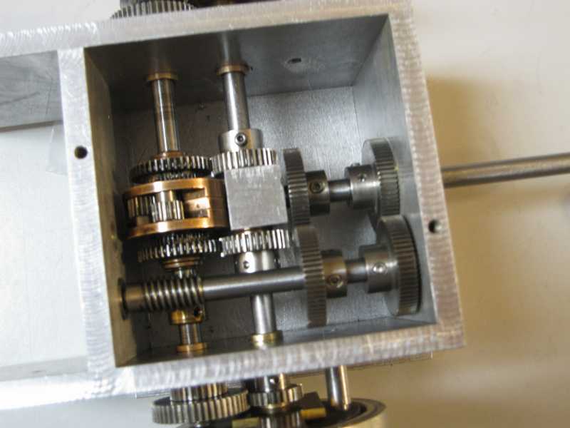
I hope to mount all the intial gears this weekend at least in trial so I might work out the selector mechanism. This needs to be on a driven shat which will be the main drive shaft feeding the worm gear. Jerry 01/08/2010
Below is a photo of where the gearbox is in progress at the moment. I placed the input gearing except the idler for one of the change gears. Even though I've tried to keep the size of the gearbox as small as I am able with this design I am beginning to have doubts as to if the gearbox will actually fit as intended into the Hetzer. I hope it does. The side plates will be cut down substantially once the final output gears are placed. What remains to be done on this project is:
As may be seen substantial work remains to be done! Jerry 01/18/2010
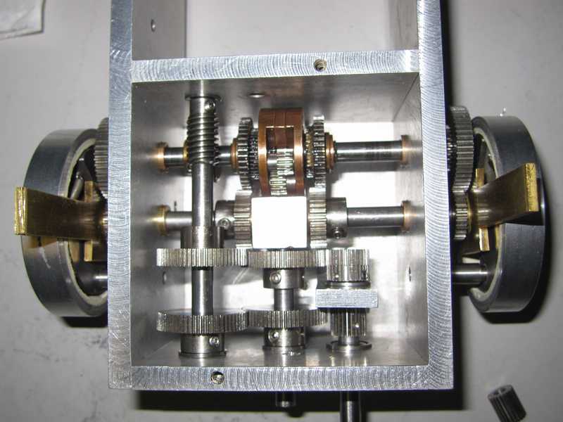
Some of the work mentioned above grows closer... 01/19/2010
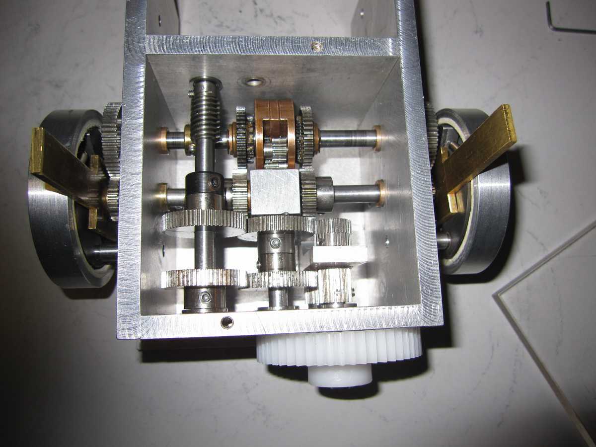
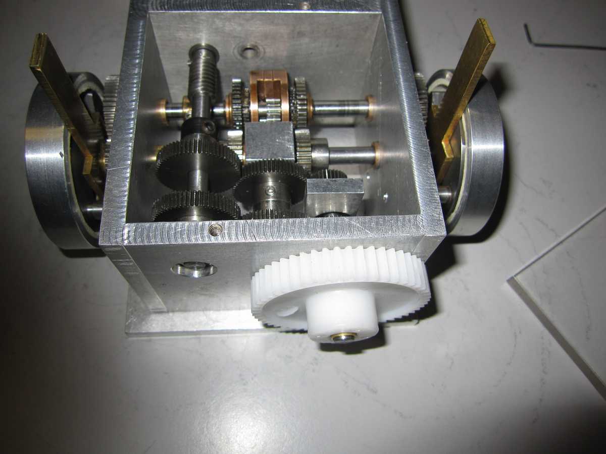
I spent some time advancing the gearbox by installing the shaft for the final output gear. It is just a trial fit but there's not much more to do to it. I'm going to wait until I get closer to actually installing the gearbox to finish the output gearing as I'm not sure if I will be able to use direct gearing or chain to engage the sprocket shaft. I'm working out the gear selector mechanism outside of the main unit. Ah yes I also shortened the front section of the side plates as the extra length is not needed. I will probably shape the ends to be slightly angled though probably mostly for appearance. Jerry 01/23/2010
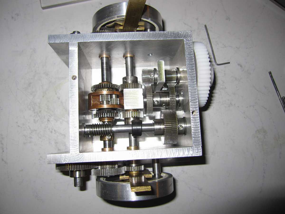
02/01/2010 I've made good progress on the transmission. The major task that remains is to work out the gear selector. I have an idea in mind and I will prove it out on some test parts outside of the gearbox. In a nutshell. it consists of a sliding disk between the 2 gears on the worm drive shaft., The nisk will be prepared with 4 to 6 holesarranged in a evenly spaved circular pattern. The disk will be keyed to the shft but movable. The two gears will be prepared with 2 pins each that will engage the central disk when it is moved up against them; the pins mating with the holes on the disk. Once engaged the input pwer to the gearbox will be transmitted along the selected mechanical path as the disk and gear will be locked together as a solid unit keyed to the shaft. To engage the opposite direction it will be a metter of disengaging the one gear and moving the disk to the opposite gear.
The additional consideration is to the actual actuator mechanism that will allow moving the selector disk into position and leaving it there while the control moves back to the neutral position. This will need to be the case from either direction
Gearbox showing it's lineage against its bigger brother: the Maier 3-speed and engine....
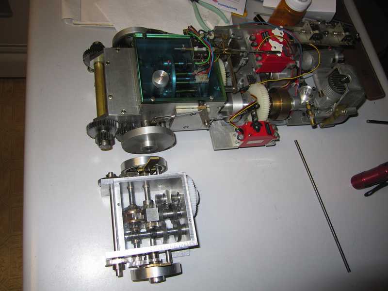
How the gearbox looks today.
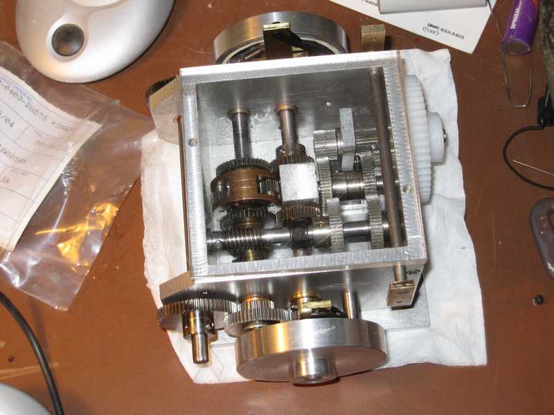
Test fit into the Hetzer lower hull. While it does fit I will need to rework some of the suspension mounting hardware; it hs struck me that while is is certainly robust it is rather the brute force approach and consunes a fair amout of space. I will probably need to set the gearbox back a ways into the hull and due to that I will probably use a chain drive in concert with an intermediate gear unit so that I may keep the operating orientation of the design intact. These component will not alter the gearbox in any way. Further and I saw this right away, I will "flip" the engine and self starter so that it is in better lignment with the gearbox input.
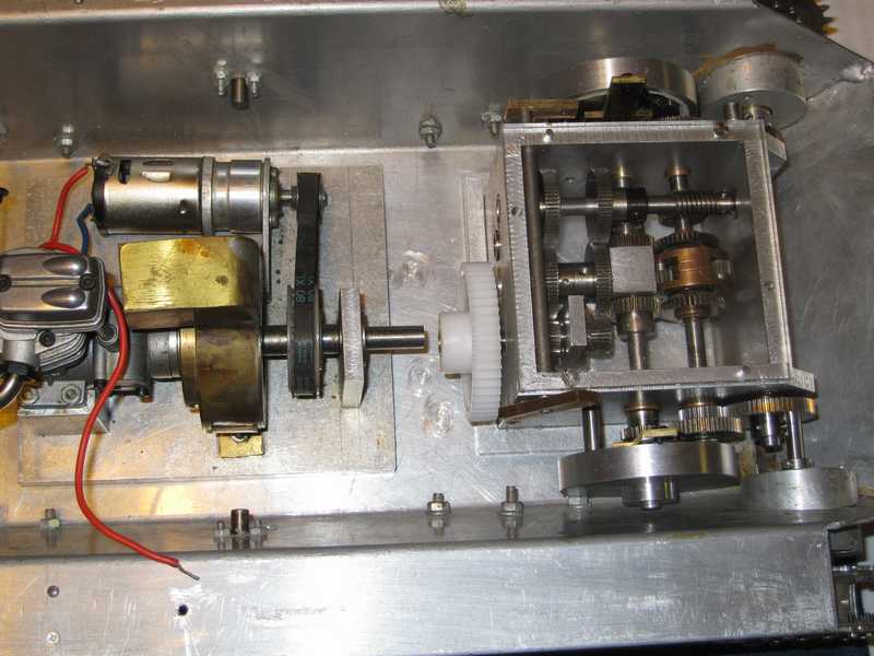
I'm taking a brief break from this for a few days while I wait for some cutters to show up. Not incidentally I'm also very aware as always with the passing of the year end and into early February marks 26 years I lost my mom and 9 years my father. Zeit fliegt. I must also add, and I've never said this that even though my two sisters and I had not been very close since we were young I miss them also; no one remains from my immediate family. I am alone. I often envy large families that manage to stay close, both physically as well as emotionally; something I never had. As fate would have it other things are converging in the same "space-time continuum" that makes one go hmmmmmm. All of this is contributing to a need to just sit for a bit. It's all good right? Stay tuned for gearbox and other tank updates, soon.
02/27/2010 - Some good progress has been made. See photo below
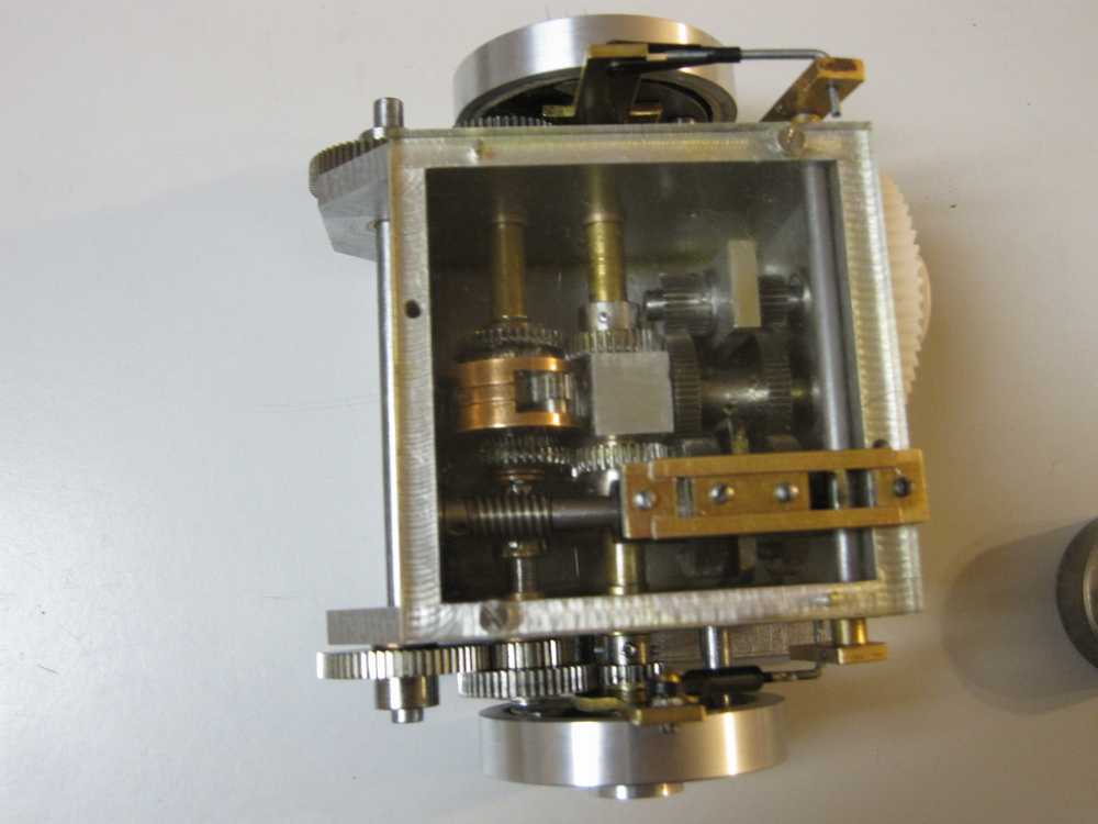
What can't be entirely seen from the photo just above is that I finally implemented a selector mechanism. It consists of a steel fork attached to a brass plate that can slide in a channel. In this way I was able to get the fork to slide in parallel to the gearshaft and selector disk and apply even pressure without wobble - a key element in getting the mechanism to function. I have yet to make an interface to this selector mechanism that will actually interface to the radio servo. What can also not be seen is that all components are now pinned to their respective shafts. I modified the shape of the brake shoes to get reliable release while the other side was engaged. The right side in particular would bite into the brake lining and lock up but that was resolved. I actually filled the gearbox with oil and ran it under power of an electric hand drill. The brake function was perfect.
I've been kicking around the idea for a while and I'll probably do it: make a new longer bottom plate on which I can mount the engine and starter - just like it's larger cousins. I should have done it at first but a longer plate would have made some of the intermediate machining operations more difficult. There really isn't much more to be done. Review some of the pins, wash the gearbox out and then refasten after sealing all joints to minimize oil seepage. I need to make an oil filler plug and possibly a drain plug although that might complicate the mounting. I've already begun working on machining the clutch plate from tool steel; a smaller version of the Schluter clutches used with the Webra 6,5ccm engine that supplies power for the Maier gearboxes....That's it for today.
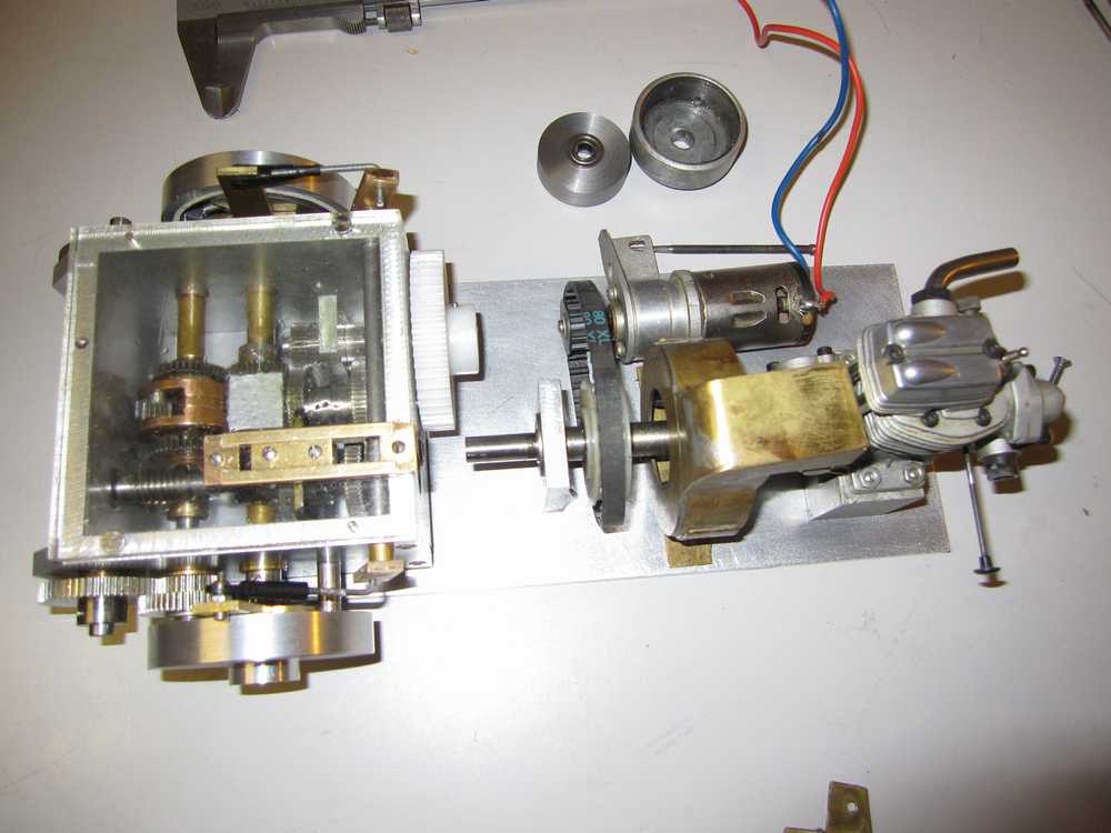
03/03/2010 Jerry here, some progress. I decided to have a go at a longer plate, see photo. While it came out "mostly" right I missed an opportunity to correct or reather improve something with which I've not been entirely pleased with. The intial imput gear ended up being a bit sloppy with too much backlash when all was said and done. This could have been vastly improved when I made the new floor plate by setting the three bearing block mounting holes over by about 3-4 thousandths of an inch when I transferred the holes from the original floor plate to the new one. Did I do this? Noooooo. Not only that BUT I managed to set this set of three holes the opposite way by some thousandths. :-( I was not happy. I will attempt to salvage the plate by filling these three holes and trying again.I will use my normal tried and true method to fill the holes; mechanically this should be strong enough but if it doesn't appear to go well I'll jut make a new plate. Everything else seems good.Tomorrow is another day. To partly smooth my ruffled feathers I laid out the engine/starter components on the plate to see how they would look. As for the rest I'm treating myself by listening to Daniel Chorzempa's recording of Bach's Prelude and Fugue BWV 543.... Later.
03/07/2010 Having been lazy I've finally made a PROPER longer base plate for the gearbox. I did take the opportunity to apply a correction to thebacklash issue mentioned above... While transfering the mounting holes I also set those that engage the bearing post that supports the input shaft over by .005" to somewhat tighten up the the enegagement of the first and second gears. This isn't a perfect solution but it should serve well. There just was too much back lash to suit me originally, so now that is done. I have begun making the clutch components and yiu can see the engine an related parts sort of propped together for an idea of what it shall look like. I've been thinking I may do away with the starter /belt assembly and change to a more 'trditional' geared arrangement but perhaps I'll just leave it. I still have to seal the gearbox and take care of a few other small items before I'll run it under power From this point the work I'll do is much like that I've done on several of the Maier gearboxes I've documented here... That's all for now..
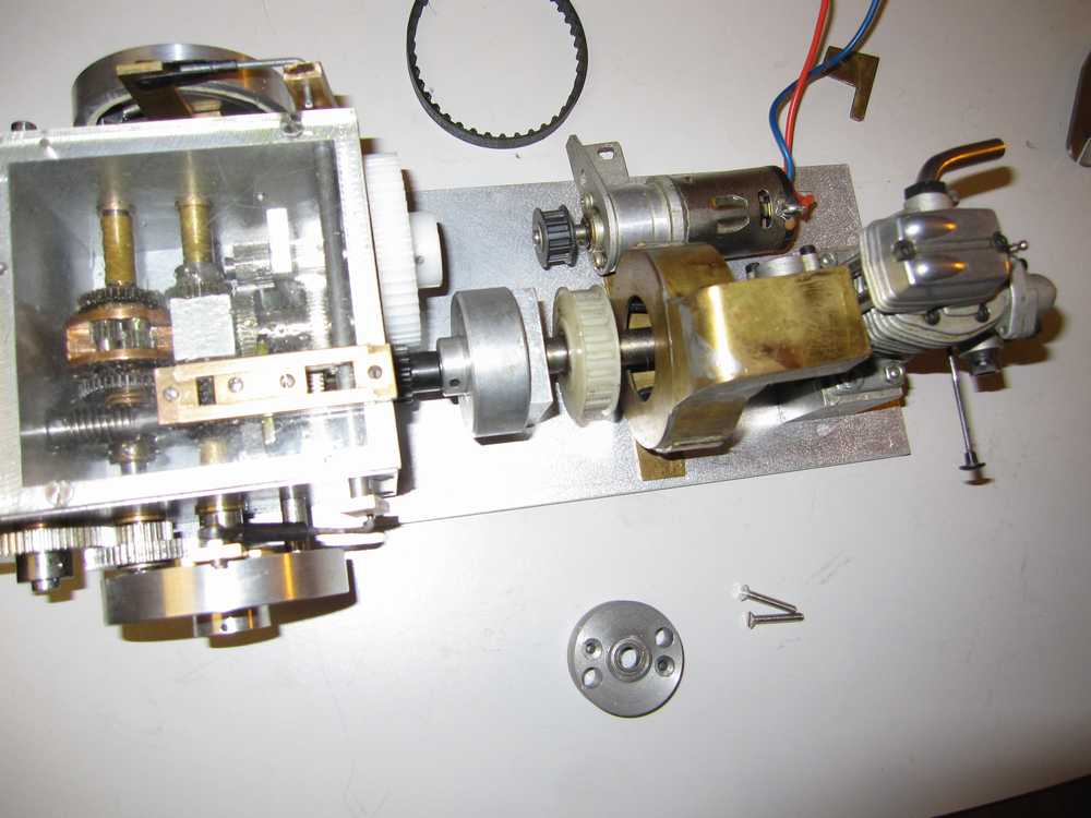
03/22/2010 This weekend I was able to run the gearbox powered by the O.S. Engines FS-20. I was very impressed with the unit's performance! Now this isn't to say how well it will actually move a tank around but the performance was very encouraging!! Please take a look at the YouTube video:
I am pleased with the results so far but as always I'm greatful the bulk of the work is done. Will I make another? Part of me wants to say yes but more of me wants to say no for it was a lot of work. If I could find someone who could machine the major components I believe assembling the units would not be to difficult. The trouble is I did this design completely in my head; there are no drawings. Sure it could be reverse engineered but that would be a tall order. There are descrepancies between the layout and the gear specifications so that would need to be cleaned up. I believe the design is solid, it could probably handle a much larger engine. I will detail the specifications below.
With this project is completed a long standing desire to create my own model tank transission suitable for glow engine power. While I borrowed heavily from Jochen Maier's layout the final design is entirely my own. The use of a planetary differential, the unique gear selector method, initial (internal input) gearing and supports as well as brake/ return spring designs are entirely my own. The Maier mid and late type multi speed gearbox will always, at least to my mind, be the best and most robust model tank transmission design ever made. I am happy to say I learned from the best.
Over the next few days I will be laying out the servos to control this gearbox. I also need to finish the external interfacing mechanism to the gear selector. After that it is laying it into the model to determine the best way to engage the sprocket shafts. I already know that due to the extreme angle of the Hetzer front hull that the gearbox camnnot directly engage them; I will need to use roller chain to accomplish that. That's all for now, Jerry
05/04/2020 - I've not stood still on the gearbox project, I've fairly well finished the last few items.
See the photos below.
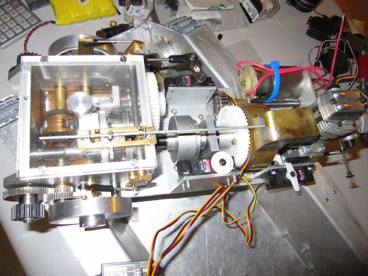
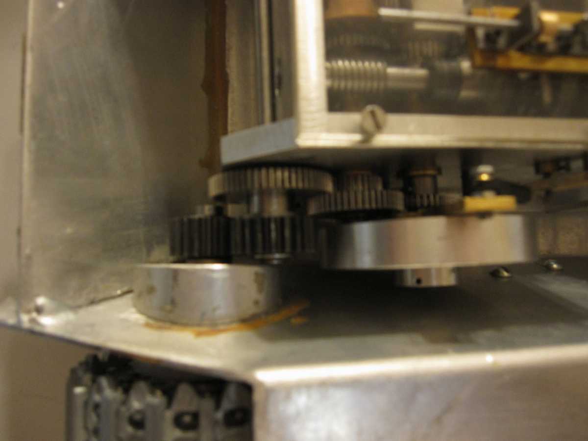

I hope shortly to finish mounting the gearbox and test it in the model. I'm afraid trying to run the model under power will highlight the weakness of the track system, from the durability as well as quality and functional perspectives however I will do my best to use it. I have to say that I was not happy with this track from the very beginning and had even contacted the supplier. While I had been pleased with this supplier, Nils Hermann, up to this time I'm beginning to have second thoughts. I'd contacted him towards the end of last year wherein I had an agreement with him ( I believed ) that I'd be able to purchase 20 or 30 spare track links each of the PzKw I, II and Hetzer. He said he would be able to get them for me early in 2010. Beginning in February frequent emails go unanswered. At this point I fear the worst.(Update 5/14/2010: Well I feel terrible. I was contacted by Nils who told me that he had experienced some serious health challenges but is on the mend. That is good news certainly! But I feel like a bum for having questioned what was happening but truly how was I to know? Anyway I am glad to hear he i well and hopefully we'll be able to do more business. I still feel Nils' models and products are basically sound.) Anyway I will continue to pursue alternates. I have asked a local guy if he would consider making a better track system for this model which I believe he can do. Hopefully we'll see. Making lost wax and centrifugal casting are two technologies I wish to explore but I am unable at present due to space limitations. The small zize of the links for a Hetzer screams lost wax or cetrifugal casting and much less so for sand casting. I have to say that these small 1/10 scale tracks in zinc make me nervous; they are so small! Well I'm hoping to try out the Hetzer this weekend on a limited basis. We'll see. - Jerry
Jerry 5/28/2010 I have mixed results after several test runs with the transmission installed in the tank. Bad results first. on two separate occasions I had gears bind on their shafts. First it was the reverse gear which bound while I was in forward gear which was odd. I had just attempted a right turn. I took the transmission apart and polished all ahafts and case hardened (thank heavens for Casenit!) the shaft which carries the selectable forward and reverse gears. I reassembled the transmission and tried again. Ran for a few minutes when I tried another turn. zzzzzit followed by light smap or pop. Transmission was frozen again. I had been in forward gear attempting a right turn. Dissassembled unit a second time. The gear that was bound? The small idler gear for reverse. Now this gear is always under the surface of the oil bath. Hmmm said I, let's think about this. One of the decisions I had made while designing this unit is that the primary gears would be steel running on steel shafts. "they're in an oil bath " I thought, "they'll be fine". Let's see: stainless steel gears running on close tolerance stainless shafts in an oil bath; top rpm 3-4,000 rpm. What is wrong with this picture? Stainless steel. Nasty stuff is not used properly. This wasn't proper. I figured two things were happening; the gears were becoming oil starved under load as they were too tight fitting and then they galled creating a burr and the rest was history. I had to change them all to run on proper bearings. I decided to use "Oilite" - type bronze bearings. Luckily I had the correct bearings already. My basis for this decision was research I did on the net which resulted in mostly hits on rebuilding motorcycle transmissions. Apparently some older designs used bronze bearings for the gear sets. I'm sure it isn't state of the art but as it was proven I decided that route( and I wasn't certain I'd find ball or needle bearings in time to get this done. So what I did was:
I tried the rebuilt transmission just prior to sitting down to write this. I ran it at full power and made coaecutive right turns, (left turns had not been adjusted back in after dissassembly of the entire unit) and it seemed ok. I will do more tests before I consder it resolved. Stay tuned.
5/30/2010 I ran the transmission in the Hetzer again yesterday for a longer run ( see video below ) and it worked very well, Still have difficulty making left turns but recerse worked quite well. At this point I'm going to say tentatively that the binding issue was resolved with the latest modification. I'll probably switch back to the Hetzer thread now as the remaining work is really sprucing up that model and working out a better non leaky exhaust system solution. I want to make a cover for the gear selector mechanism to keep dust out and eliminate and oil spray but I don't see this as a big issue. - Jerry
Rebuild and conversion of Maier manual 3-speed transmission
12/26/2010 - Hello all. Somewhile back in early November of this year, 2010, I had the opportunity to purchase another example of Jochen Maier's excellent 3 speed tank transmission. I'm going to resist the urge to lambaste some previous owner who made modifications to the unit. All I will say is it appeared to be an attempt to convert it from Maier's manual gear selector mechanism to a some sort of worm drive motor driven mechanism. I only saw the partial results of this as several parts were already missing when the unit appeared on ebay.de as part of an earlier vintage Maier Panther. When the tank didn't sell I approached the seller and asked if he was interested in selling the transmission separately which he was. He stated a price, I accepted and here it is:
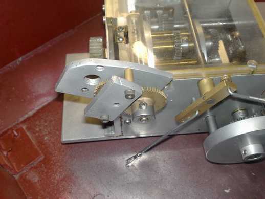
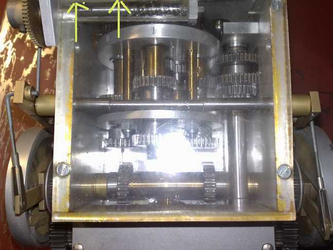
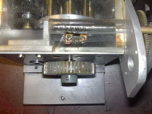
I knew what I was getting my self into: basically a lot of work. I don't why I do, but I really enjoy rebuilding things like this. Perhaps because it allows me to 'rescue' some forlorn mechanical thing that would possibly have come to further grief had I not intervened. That sounds rather pompous even to me. Let it suffice I enjoy the challenge.
I quickly decided on taking the transmission apart it should be easier to convert the unit over to Maier's ecetrically driven selector mechanism than to try and recreate the parts for the manual mechanism. I ordered the 2 gears I needed from SDP-SI: 1 steel module 1 60 tooth gear and 1 module 1 15 tooth gear. What follows is the conversion effort.
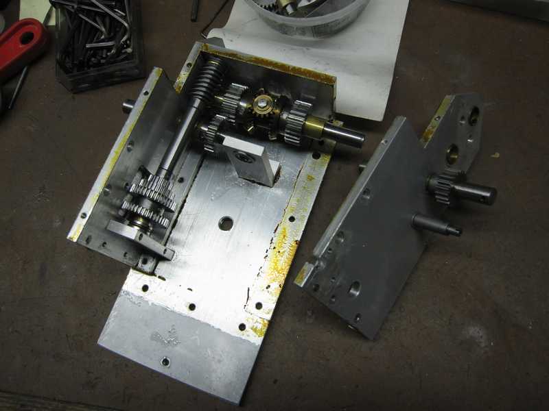
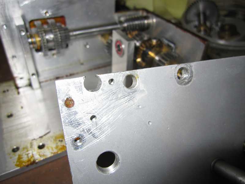
First order of business was to fill all the holes. Below you see the side plate with the worst holes now filled.
Maier must have used his existing stock of side plates for example because one of mine has the holes of the manual selected version filled with screws. It's possible he upgraded some himself at customer request I suppose. I chose to fill in all the non- original AND original holes on the side and front plates using my usual methods except for the one large threaded hole on the right sideplate. For this one I chose to use the method Jochen used himself which was to make a threaded brass plug for it. On the original manual 3 speed transmission this hole was used for a type of adjustable support device whch Maier eliminated with the later selector mechanism.
Maier later beefed up some components in this design; notably the forward mount point of the gear carrier but I have several examples of his early components used in the first versions of this design. I may consider making the beefed up bearing pillar block that supports the gear carrier but this isn't a priority for me.
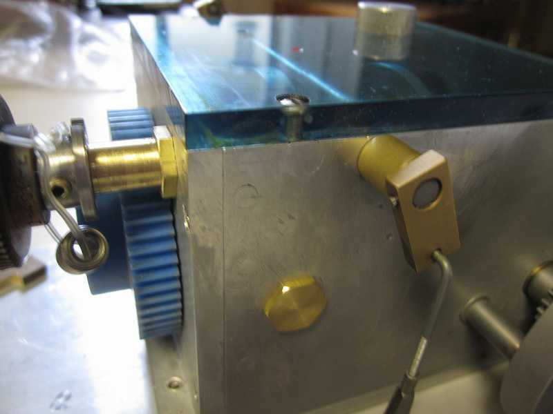
I have made all the parts you see except the plastic cover, that is a spare original from another gearbox I have ( used in the JagdPanther described elsewhere). I will make another cover though as I want to keep this one original. I was able to get a small section of 6mm fluorescent transparent Plexiglas similar to what Maier used. I always liked the effect it had. Mine is blue. I'm going to leave out all the intermediate steps in making all the parts needed to make up the selector mechanism but will probably show them laid out to be thourough.
Below if the main gear carrier being fitted with the 60 tooth module 1 gear appropriately machined to fit.
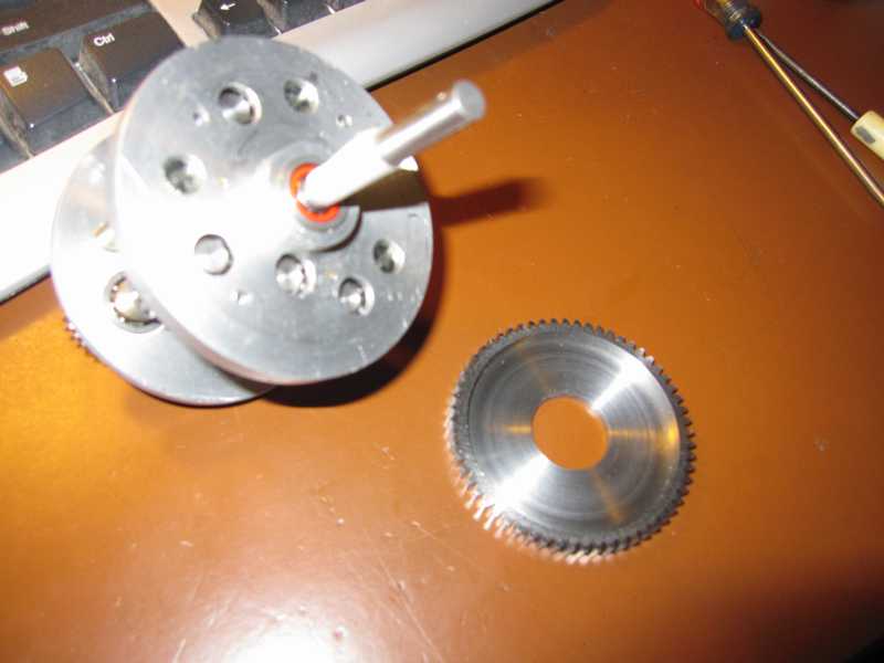
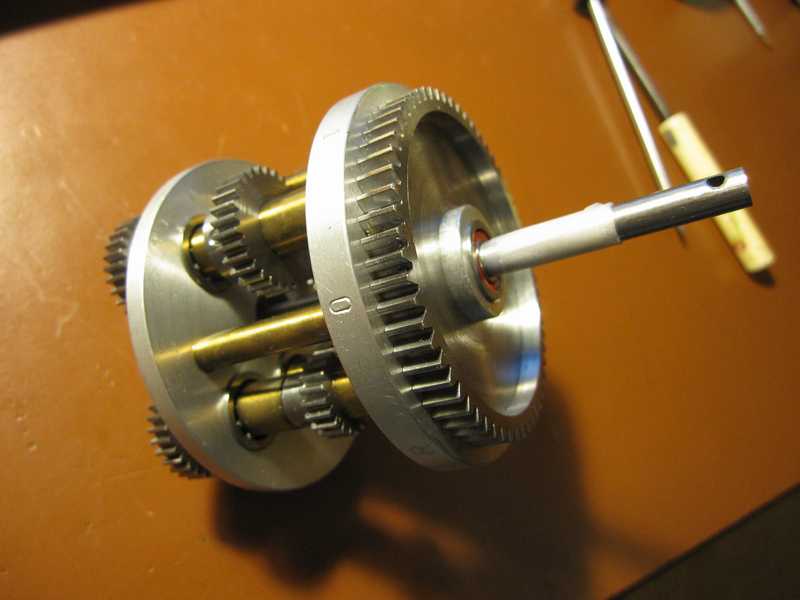
Maier's last gear selector design was very clever. He has the gears distributed about a circular carrier with a 'neutral' between each one. This makes 8 'stations. The gear ratio of the selector mechanism is 4:1. There is a metal disk on the selector shaft with 2 notches cut into it at 180� apart. 2nd grade arithmetic shows us that these will divide each rotation of the smaller gear into 2 180� movements. 2 x4 =8 allowing the gear selector to be 'timed' to stop the rotation of the gear carrier at each of the 8 stations in turn for every half rotation. At a leter point I will diagram this for clarity
More progress 01/11/2011
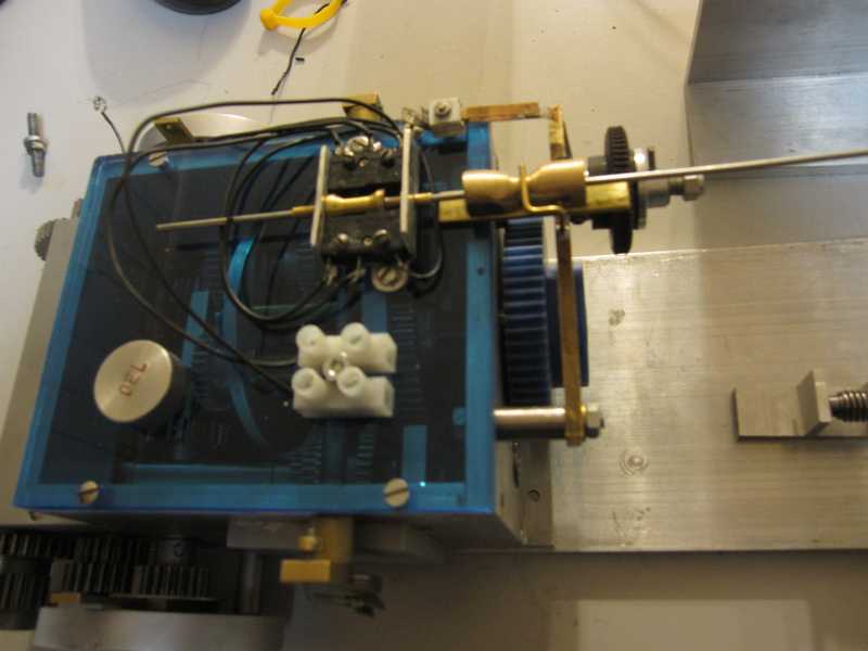
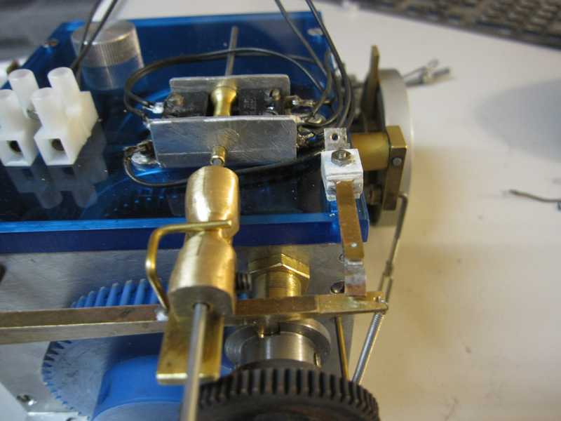
01/14/2011 - As may be seen from the photos above I've made significant progress for the upgrades to this transmission. All that really remains is to make the motor mount to drive the selector mechcanism and make the final form of the wiring. I duplicated the gear position markings from the rear gear carrier disk onto the front disk so that they may be seen easier. I noticed that Maier did this also on his later examples only he when constructing a gearbox only put them on the front disk. The reason behind this is that on the manual selctor the original markings were readily readable but the addition of the components needed to control the electric version obscured these requiring a new location.
When these initial changes are complete I plan to shoot a video of the selector mechcanism's functiom. This I hope will clear up any questions about how it works. - Jerry
01/17/2010 I have completed all the changes I wish to make at this time. As I want ultimately to fit the standard Webra 6.5ccm / .40 cid "Blackhead" engine to this transmission that is a whole other project. As you know by now I've done this a number of times so there isn't anything new there. I'll post a photo when it is done but there are some other things that may take precedence. I'll post the last few photos of the work I've done here with with a brief explanation by each.
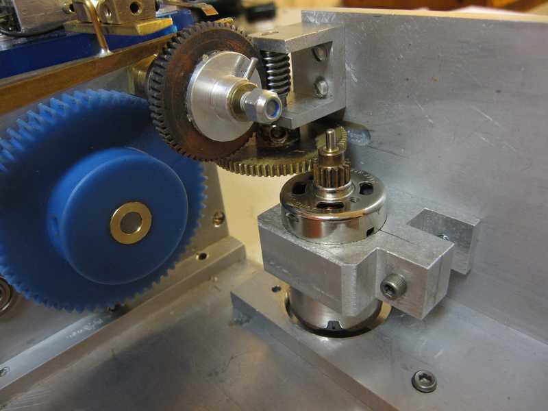
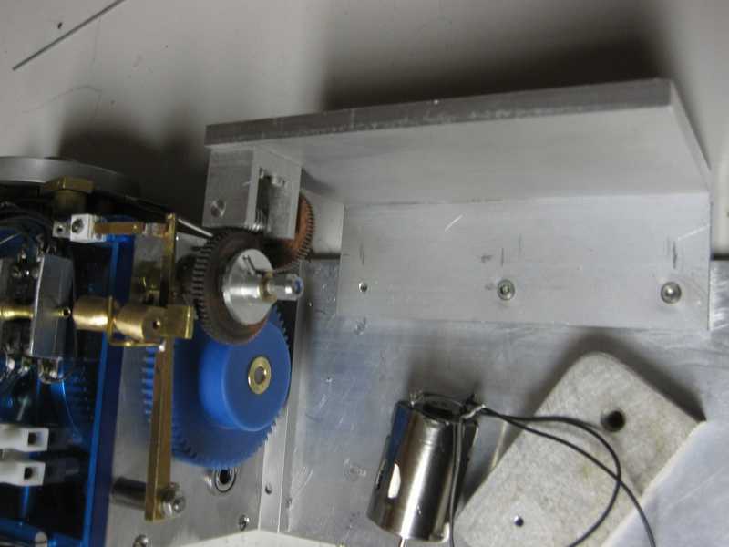
This photo shows the electric drive motor/ mount that drives the gear selector.

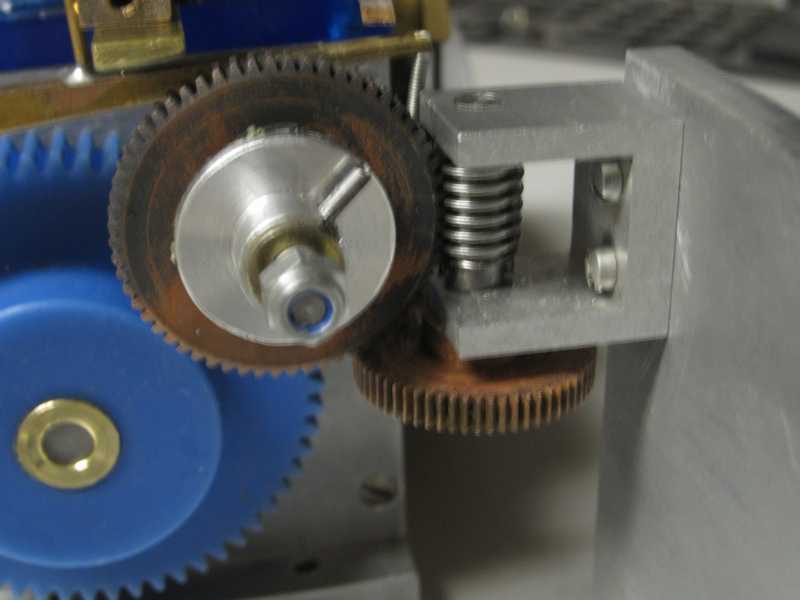
This photo shows the electric drive motor and gear train to drive the selctor shaft. Those observant among you will notice that I changed the driven gear on the worm shaft; this was due to spacing issues with the previous gear which was really too small. The ratio of this and its pinion are about 5:1.
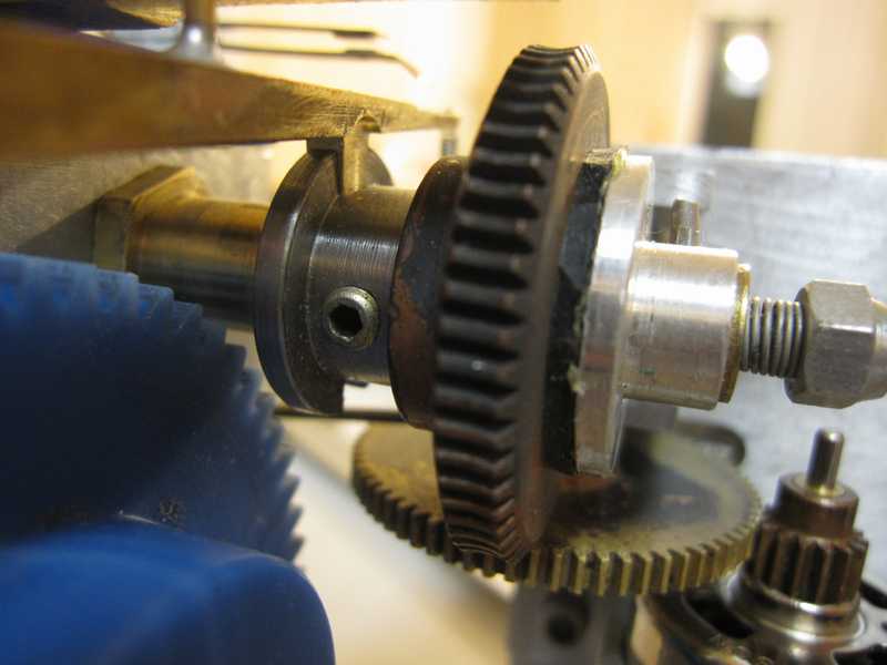
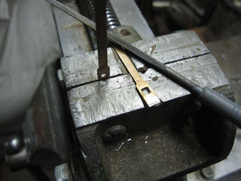
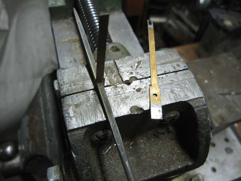
This photo shows a closeup of the selector lock, the odd shaped brass piece that has a tab locking in the notch on the cam of the selector shaft ( just to the left of the worm gear hub ). This cam has two such notches 180 degrees apart as mentioned earlier in this article which allow positioning the gear carrier at each of its 8 positions. It's rather hazy but at the far end of the selector may be seen the fingers of the activation switch. When the selector actuator is slid on its track and raises the selector lock it also causes the activation switch to close sending power to the drive motor.
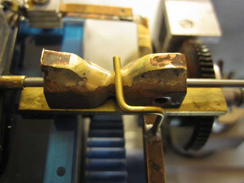
This photo from above shows the selector actuator, sort of a hypbolic parabaloid ( No I didn't make that up! Refer to HyperbolicParaboloid for the definition) that slides back and forth under servo control. By its shape it forces the selector lock to disengage and closing the activation switch allowing the drive to move the gear carrier drum either up or down in the range ( 0-1-0-2-0-3-0-R or opposite). The idea is that once the selector is acitivated the servo is released to regain its, and therefore the selector actuator's, center position. The elector lock is at this time riding on the rim of the selector lock until the lock falls into position into the next position and also deactivates the motor drive. This is done repeatedly by the operator until the desired position is reached. As may be seen the shape of the selector actuator that I made it exagerated; I did this purposefully to make sure the selector lock clears the cam when the motor is engaged. It is this mechanism on Maier original gearboxes that I've seen so much violence vented. It actually works quite well but needs attention from time to time and above all lubrication.
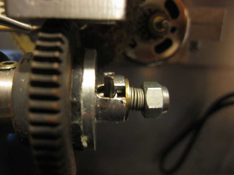
This photo shows another misunderstood component in this mechanism: the interface between the driven worm gear and the sliding drive dog pinned to the selector shaft. The drive dog has a rubber -like 'sticky' surface and is under slight spring pressure. It is key that the drive dog may be free to slide - note enlongated hole where the pin is. This freedom allows the pressure on the worm gear to be adjusted. As I made all these parts I used innertube rubber for my interface layer. This mechanism protects the gearbox from bring damaged by the selector mechanism should it become jammed. It will easily slip under those circumstances. While it is truly a sensitive balance it's much better to slip than ruin the gearbox.
I make slow progress even under the best of circumstances as I try to think things through, albeit with varying degrees of success, I'll work for a while, stop review my sketches and proceed. In this case I could really find no 'off the shelf' components to use even for what you would think as simple components auch as the relay fingers -type switch, the micro switch block; in fact the only things which I purchased in component form is the white terminal block. Everything else I had to make. Thatmakes 'just getting there' half the fun..
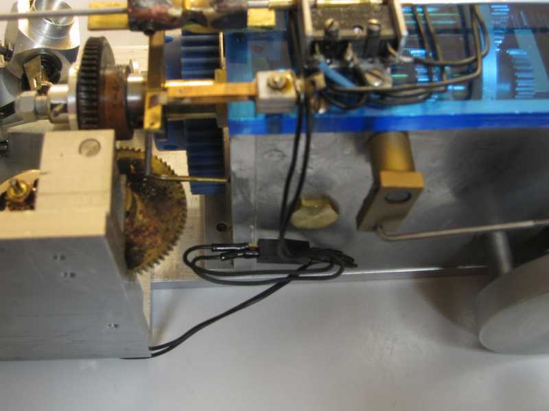
This photo shows the mechanism from the other side and that I decided to use a plug to connect the motor. Easier to service just the motor should the need arise. I've only had to service one othese motors once so I never modified my other gearboxes to have this but while I was doing this I thought what the heck. As may be seen in these later photos I have made a new cover plate ising the iridescent blue .250" plexiglas sheet. I rather like the effect over the dull clear I used on a previous cover; I may revisit that one...
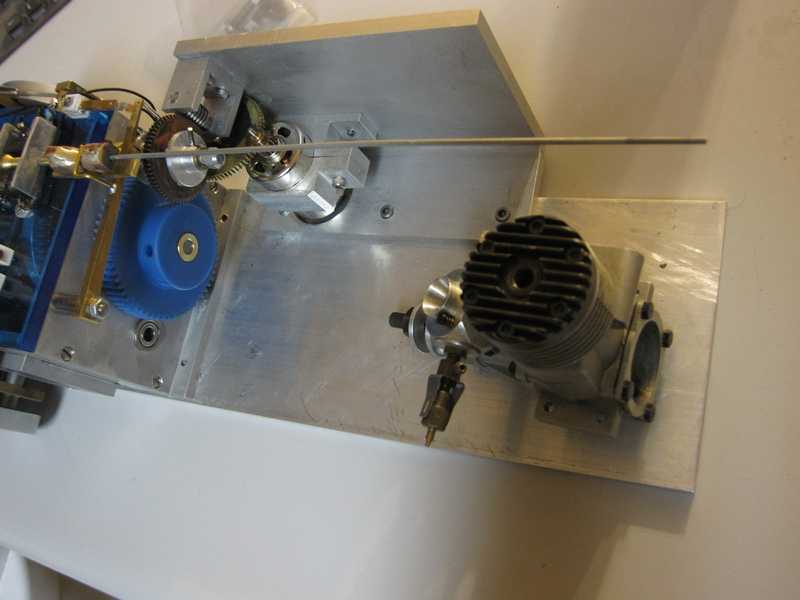
This just shows where I'm parking this for the moment. I've selected a motor to modify. I detailed this in another article so I'm going to take care of other things while I gather the materials for this part of the gearbox upgrade. -Jerry
I'm baaaaaack... 02/24/2011. Progress as usual is little by little. I've spent time on the engine I had selected to covert it into the rear fan, 'Stamo' version. The work is mildly tedious mostly as I haven't perfected a method of making the components from smaller stick keyed and brazed or screwed together. The rotor that engages the crank pin for example has a disk that is about 1" in diameter and a shaft of 7mm requiring me to turn it from a 1" bar of steel. That operation takes me a while. When I have time I want to further my tests with composite parts but for the moment it is done.
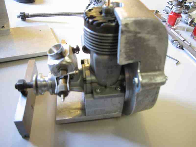
The engine as modified, monunt was constructed from .250 aluminium plate. I didn't have a cast mount to use and knew it would be months before I even consider doing any castings.
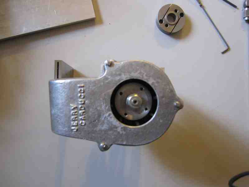
the fan end, I used the boring head on this casting to 'pretty' up the opening.
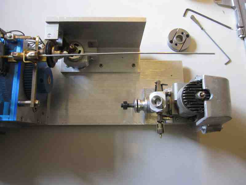
Waiting to make up the flywheel and the rest of the powerline. At the moment I'm waiting on the arrival of some chucking reamers I need to finish the bore in the flywheel. Odd thing that. I hadn't realized but there is substantial variation in the diameter of the crankshaft nose for different examples of the Webra Blackhead 40 engine. I don't recall the exact pitch of the threaded part but it is more the unthreaded part that seems at issue. I recall purchasing a .236" reamer years ago to bore a part for another Webra .40 but this one has a diameter of .239" and another example I pulled from my backups is .249". This I'm sure is boring to just about 99.9% of everyone reading this but when you're faced with finishing a part it becomes really interesting. The size .239" falls right in the middle of a gap I have in my drilling / boring equipment. So I needed to first wander that online auction house where luckily I was able to find the correct size. You can't just bore something like this "close"; it is a massive part that will be driven at 10- 12,000 rpm. A few 001" off and vibration will eventually cause damage. There's enough vibration from a single cylinder engine at the best of times. This is part of why things take me so long. I'll do other things while I wait but this project is stuck for a while.
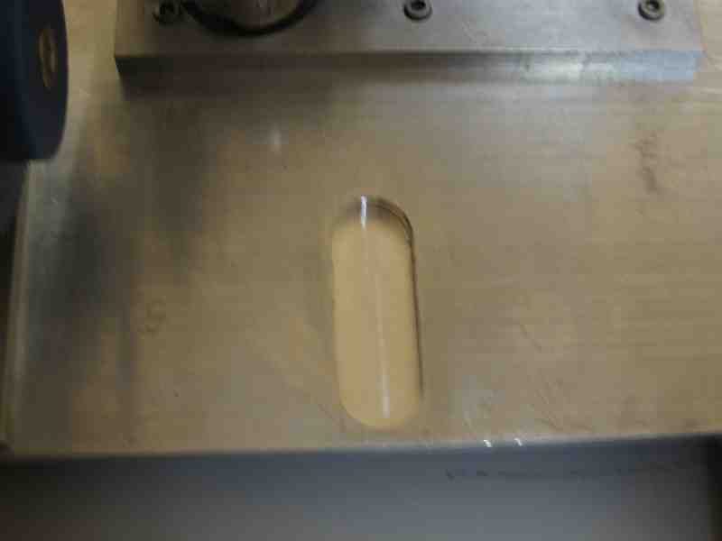
Below you may see the slot I milled for the starter gear
Below you may see the progress so far. I'm waiting for a flanged 10mm bearing for the support block that you see off to the side, the "L" shaped piece. More as this progresses.

Below you may see the progress up today 04/04/2011. The engine is mounted, mostly. As with many of my projects I will set this one down for a while. I do get burned out and these projects require a lot of machine work. I will clean up my machines after I make the gear carrier for the starter. That's the last major component to be made for this. These projects are great for winter but as we approach summer I'd rather be outside either running a model or just playing in the sun... Jerry
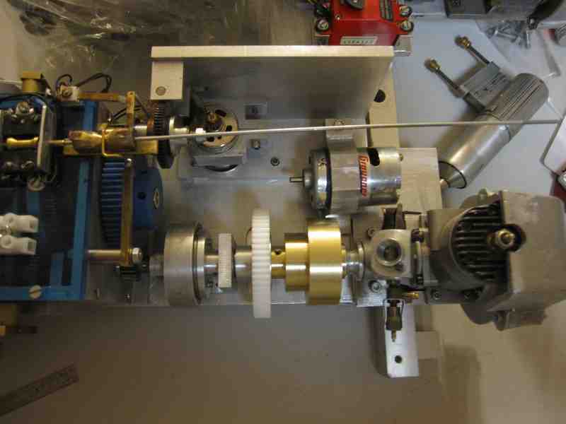
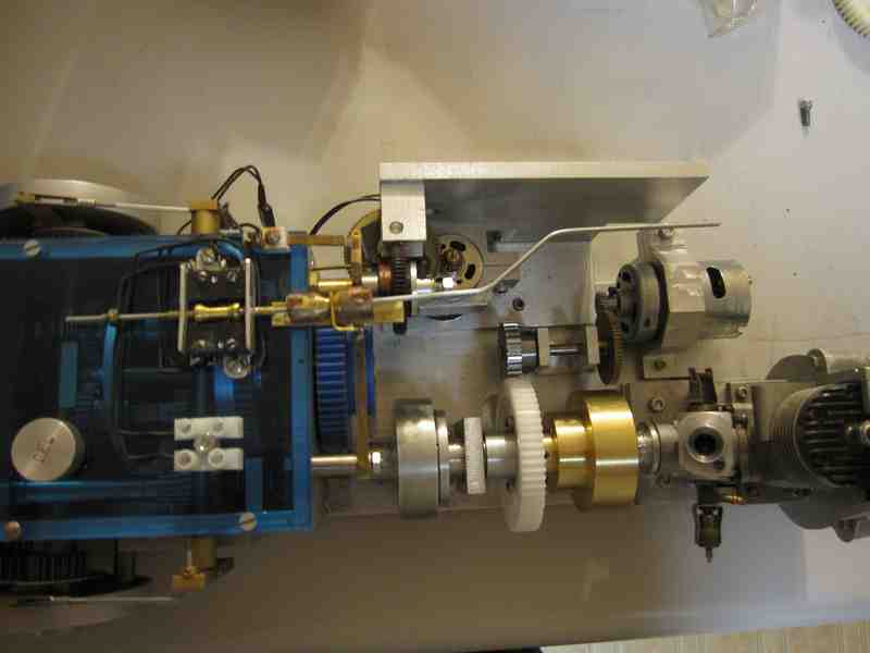
Below you may see the progress up today 04/17/2011. Everything is mounted where it needs to be. I tried the starter and it turns the engine over quite handily. I will put this away for the moment even though there two final screws and one pin to be installed. I also must seal the gearbox before putting in the appropriate amount of oil.I am satisfied that this repair and upgrade is complete enough to allow me to move on to other projects. The installation of servos I would wait until I know what I will be installing it in. This was an enjoyable project Jerry
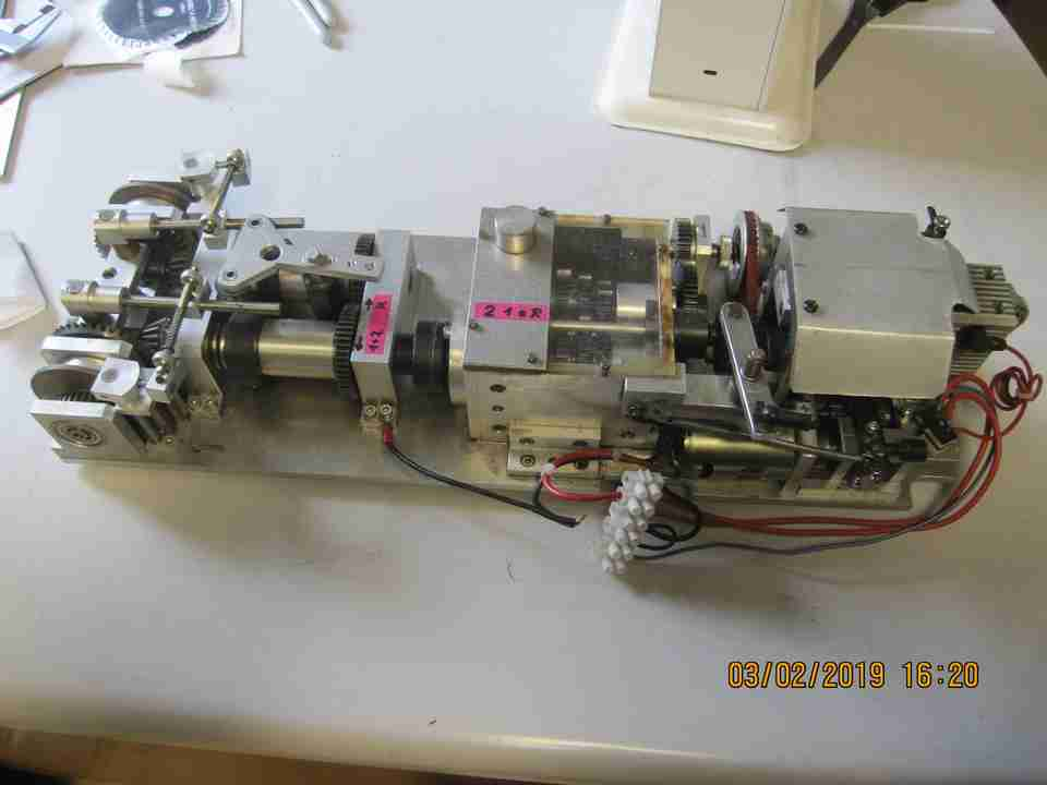
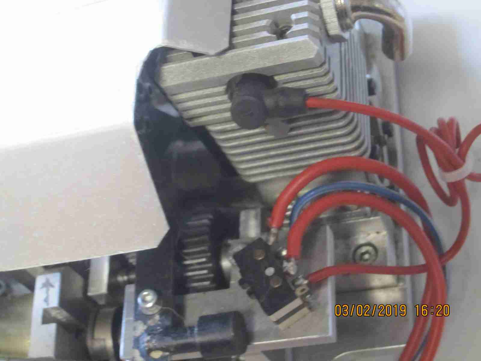
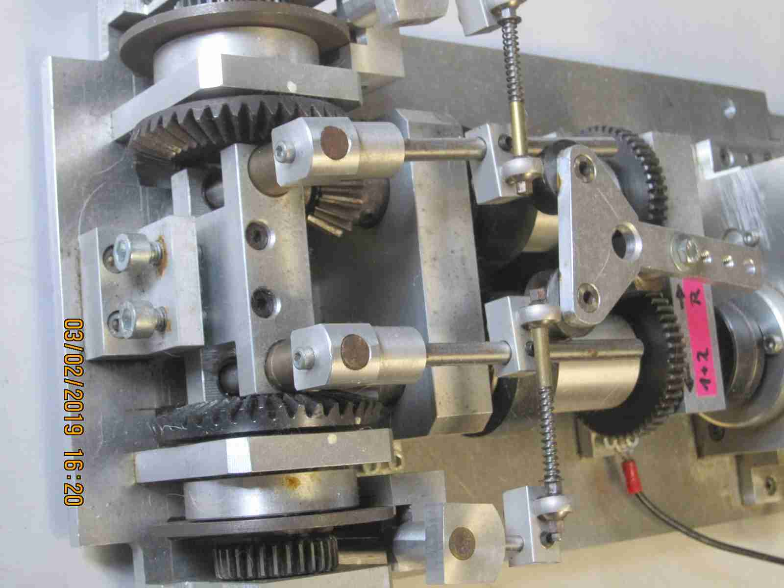
Here's something different. A two speed gearbox+ reverse of unknown origin. I found this up for sale on a forum in Germany last year( 2018) and purchased it. As far as I am able to determine there is no indication as to who made it; no part or serial number nor any distinguishing stamps or engraved characters. It is extremely robust and heavy weighing a whopping 18.25 pounds ( 8.3kg). The seller had it displayed within the hull of what appeared to be a Maier-type / size Panther hull which is what prompted me to buy it however I know little of its functionality nor if it actually works at all. One of the unique aspects of the unit is that it is powered by a Webra .40 T4 4 cycle engine. It appears either never to have been run or at best run very little. Jerry 03/02/2019
A Maier single speed gearbox- refresh
I'm always on the lookout for an original Jochen Maier tank Transmission, any vintage, type or condition really although the open faced 3 speed forward/reverse early types are of marginal use. I do enjoy rebuilding them because they're so well made and 'meaty'.
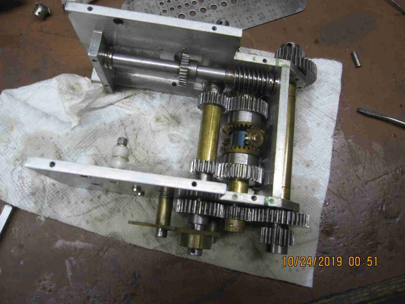
Some time ago, I can't recall wehn exactly I had the opportunity to purchase what I've come to accept as Maier's later style single speed forward/reverse type gearbox- transmission (I tend to use gearbox/transmission interchangably although I don't really know if that is correct). I did buy it and upon receiving it made a new longer bas plate and put it away. Recently while I was either rummaging through or rearranging parts of my 'model stuff' I pulled this thing out and began fiddling with it. I recalled that when I'd first received it the gearbox was very difficult to turn by hand. It seemed to have become worse. At first I thought the brakes were binding but that turned out not to be the case. Long story short the problem turned out to be that a gear which is supposed to run free on the end of the differential shaft had bound up, galled or 'turned a burr' as I've heard the expression. Below you can see the shaft and gear that were invlved with this. I may have made the situation worse by trying to get it to function but I doubt it. These gearboxes are designed to run in an oil bath of about 1cm and through seepage through the various bearings all of the external gears and shafts are normally well lubricated. I ended up completely disassembling the gearbox to correct this problem. I polished all of the shafts, filled various spurious holes which had been made by some previous owners. Once I was satisfied everything was as it should be I reassembled the unit resealing all the housing plates and other parts with lacquer.
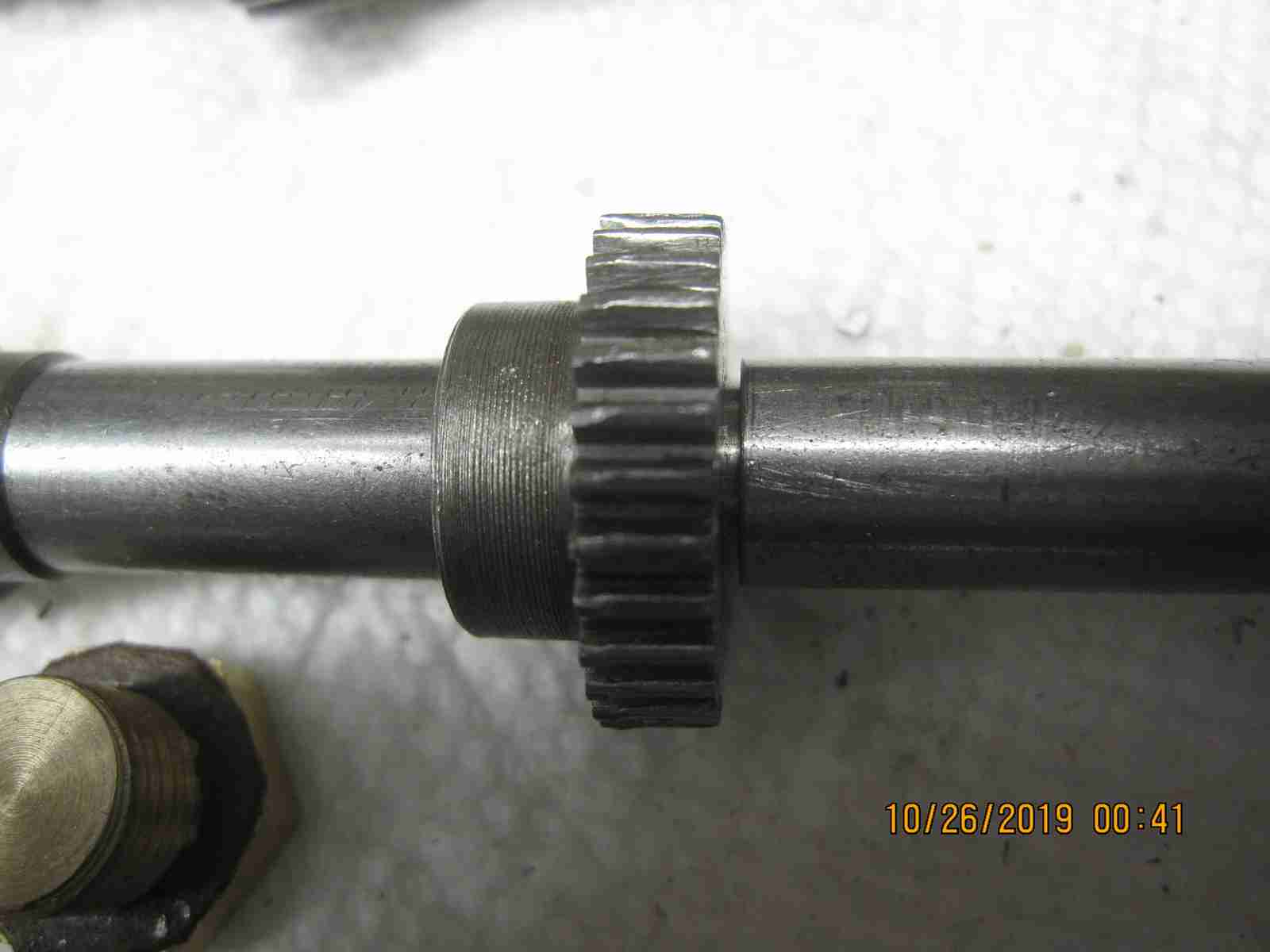
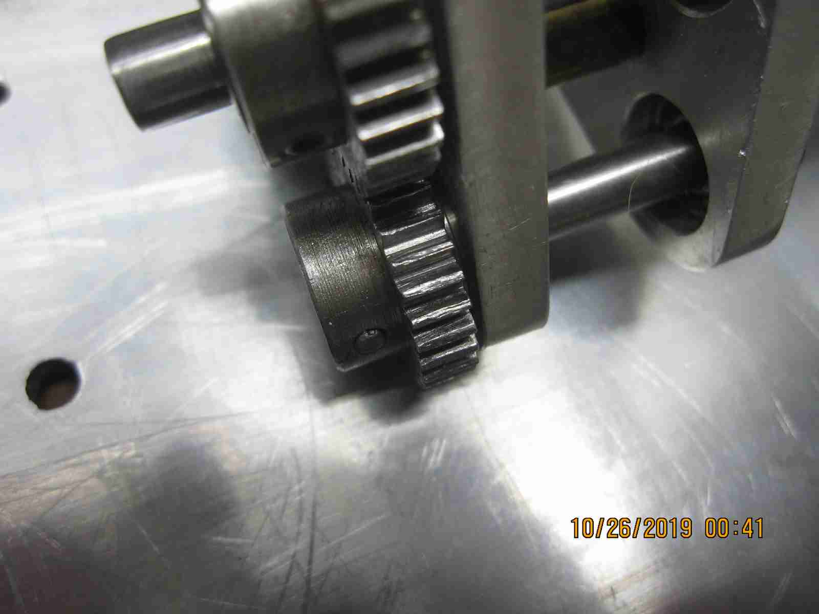
I should point out that during the disassembly and inspection I realized that the selector gears for forward and the driven gear are badly worn to the point of the gear teeth being deformed. Usually I've seen this sort of wear when one of these units was coupled with an electric motor and run a too high of a speed for prolonged periods. I should change the gears but all I dis was to clean them, reprofile the teeth with a jeweler's file which should allow more use from the unit. I will make sure the gearbox is used only with a glow engine asnd only with appropriate oil.
The unit now works perfectly, as it should and at some point I will fit a webra engine and starter to it. Also a mount for a dedicated servo to control forward an reverse selection as this type doesn't have a index capability to keep the selector in one position. See the photos below for thr assembly. This unscheduled 'refresh' was a nice short break from my other projects. Jerry 10/27/2019
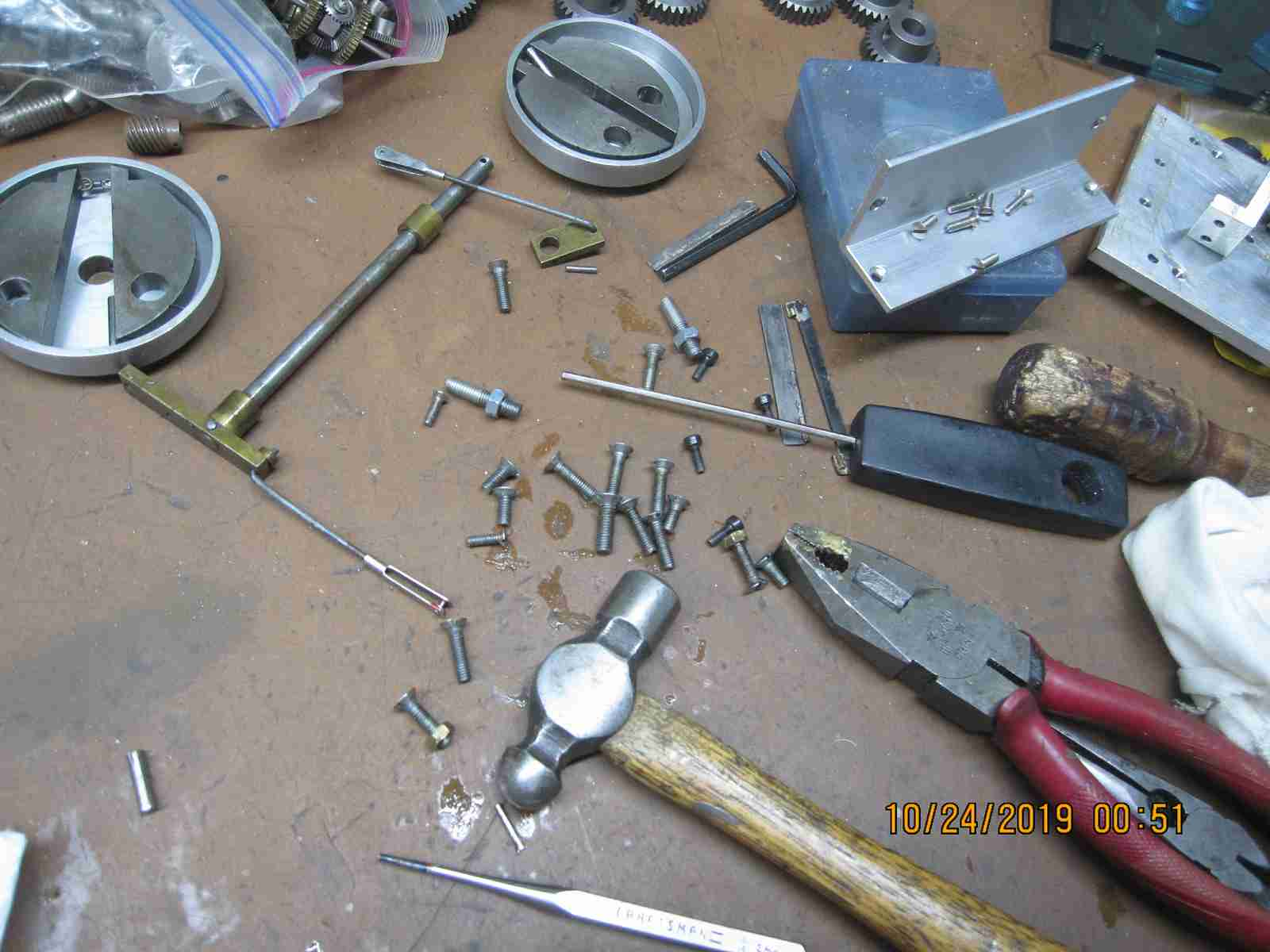
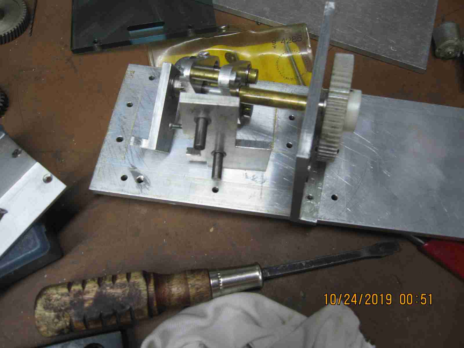
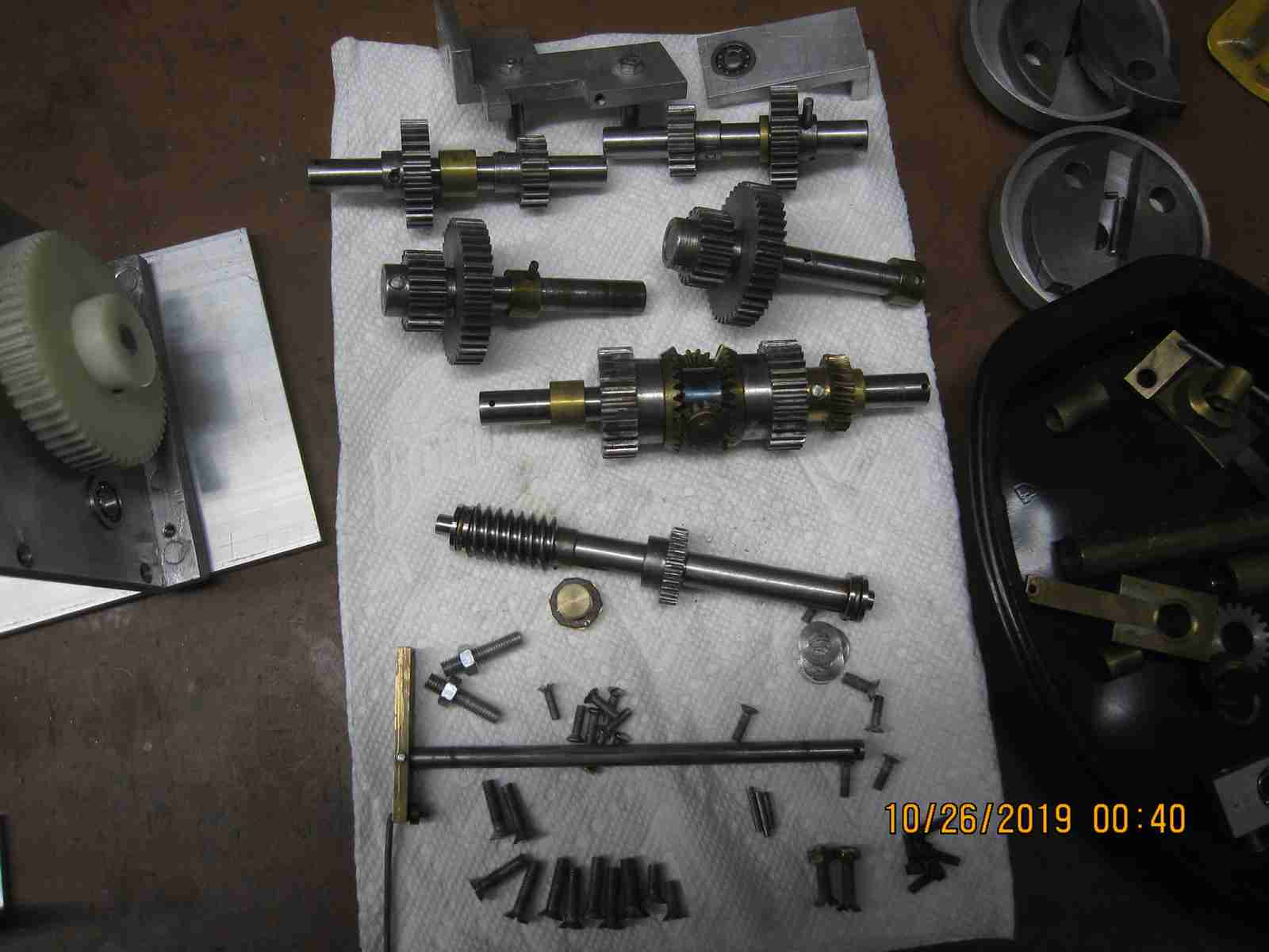
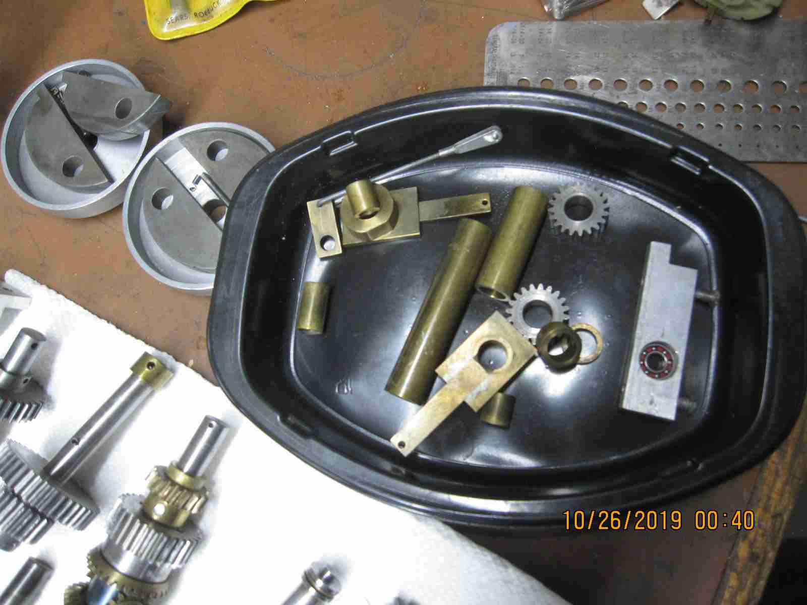
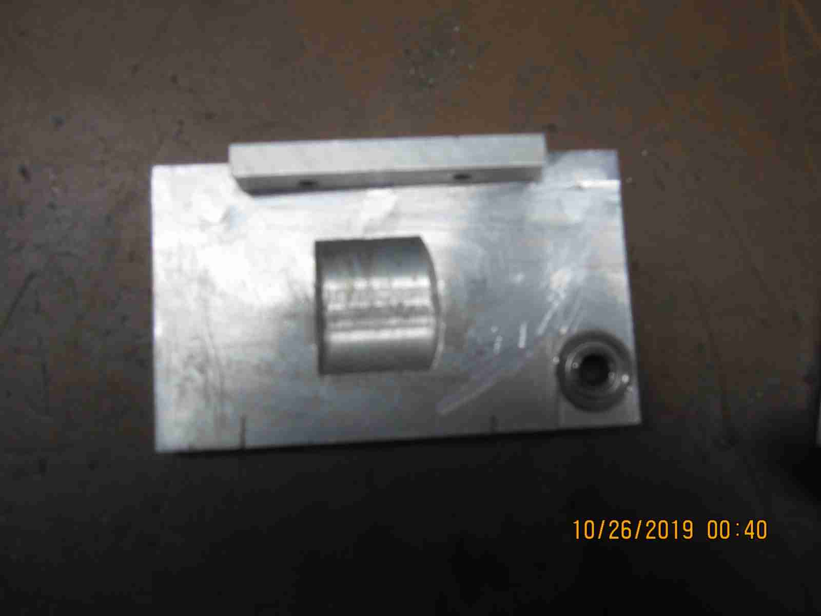
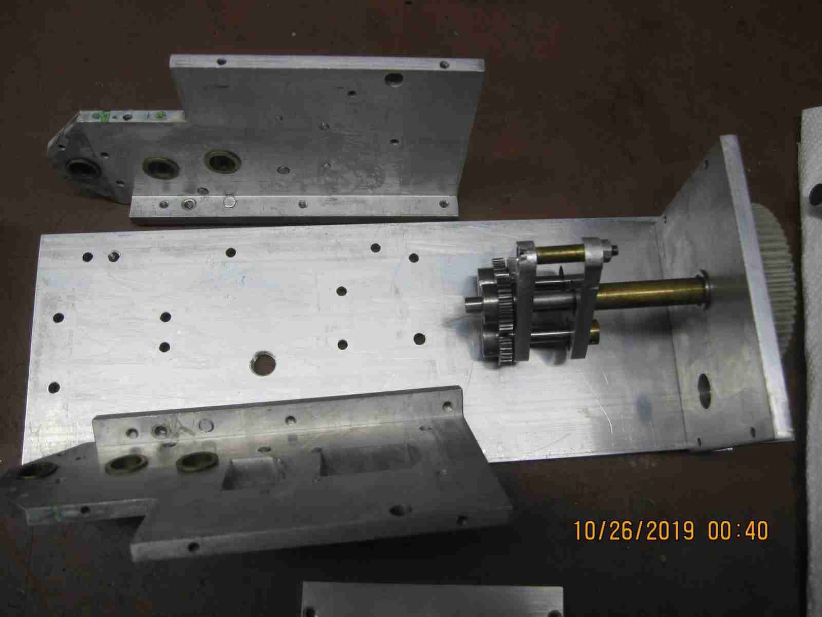
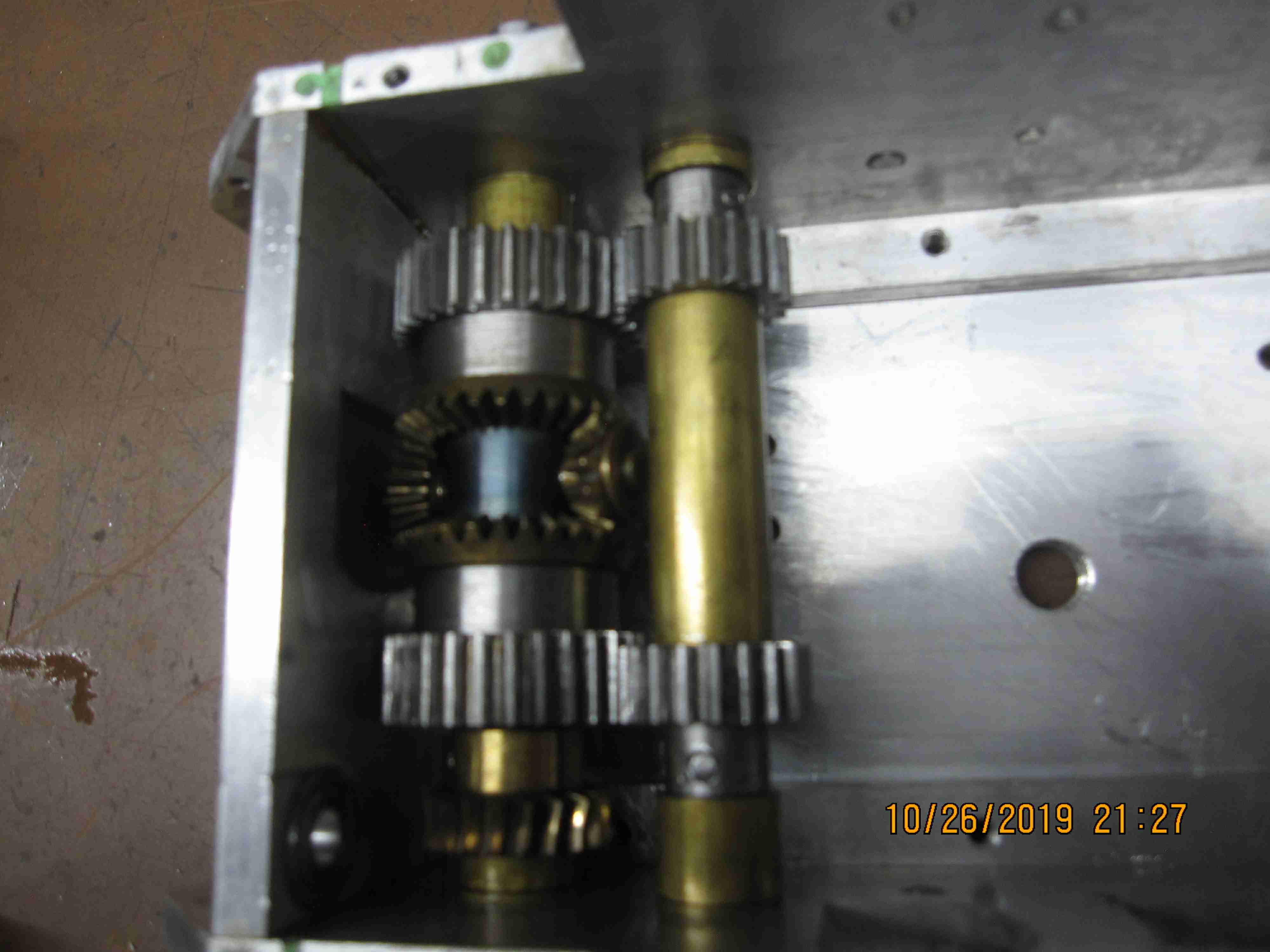
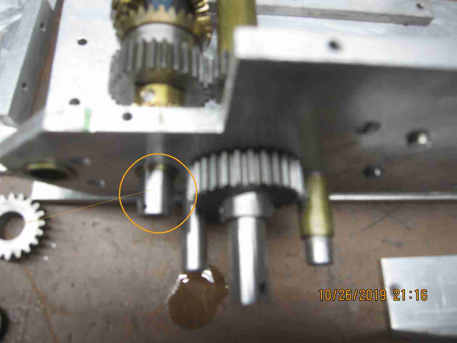
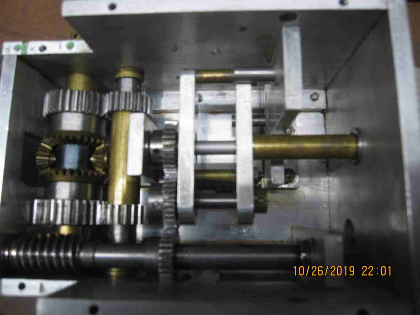
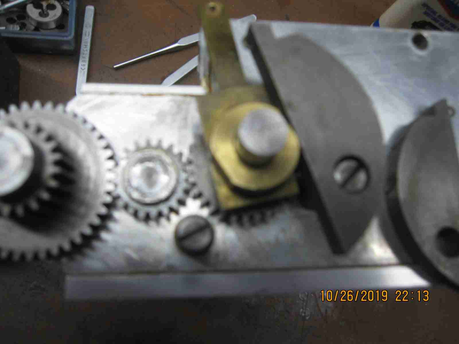
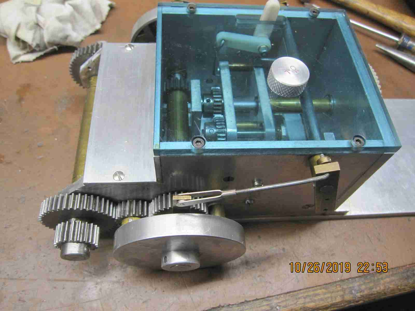
Below are two photos showing the damage that had been done to the selector gears, Deformed, chipped and generally mashed teeth speaks of improper gear shifting, power still being applied- clutch not properly disengaged and running at too high of a speed likely this was done using an electric motor for power. The high speed could also account for the gear binding on the shft mentioned above. I expect that running with the appropriate glow engine and properly functioning clutch along with proper lubrication will prevent a recurance of this issue.
---o0o---
---o0o---